1_H24维修手册.pdf - 第198页
E d i ti o n 5 .0 H 24 H ead R ep ai r T r ai n i n g T ext f o r S er vi ce E n g i n e e r s I PS C a m e r a p o s i ti o n a d j u s tm e n t fo r H 2 4 h e a d u s i n g h e a d b e n c h 2 . 5 A dj us t i ng t he C…
Edition 5.0 H24 Head Repair Training Text for Service Engineers
IPS Camera position adjustment for H24 head using head bench
2.4 Configuration Settings
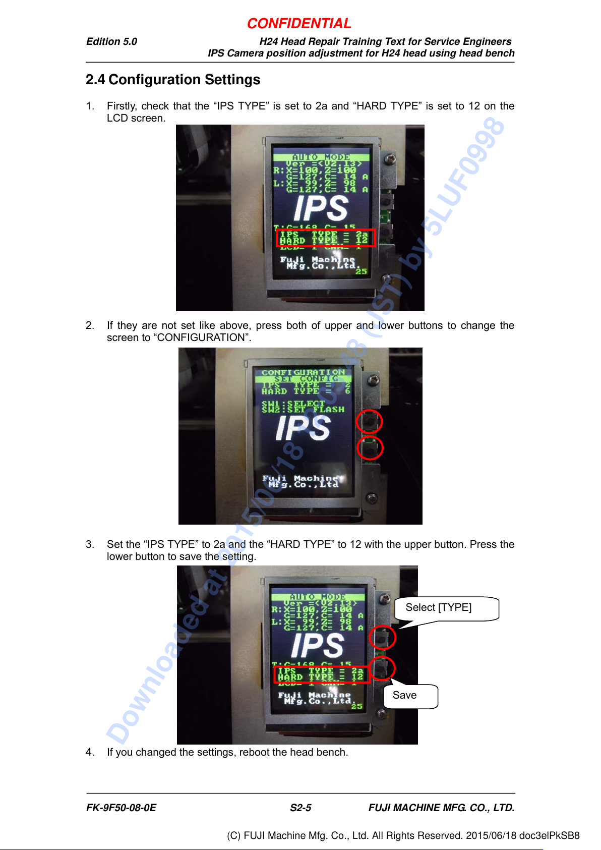
1. Firstly, check that the “IPS TYPE” is set to 2a and “HARD TYPE” is set to 12 on the
LCD screen.
2. If they are not set like above, press both of upper and lower buttons to change the
screen to “CONFIGURATION”.
3. Set the “IPS TYPE” to 2a and the “HARD TYPE” to 12 with the upper button. Press the
lower button to save the setting.
4. If you changed the settings, reboot the head bench.
Select [TYPE]
Save
FK-9F50-08-0E S2-5 FUJI MACHINE MFG. CO., LTD.
CONFIDENTIAL
Downloaded at 2015/06/18 12:05:48 (JST) by 5LUF0998
(C) FUJI Machine Mfg. Co., Ltd. All Rights Reserved. 2015/06/18 doc3elPkSB8
Edition 5.0 H24 Head Repair Training Text for Service Engineers
IPS Camera position adjustment for H24 head using head bench
2.5 Adjusting the Camera Installation Position
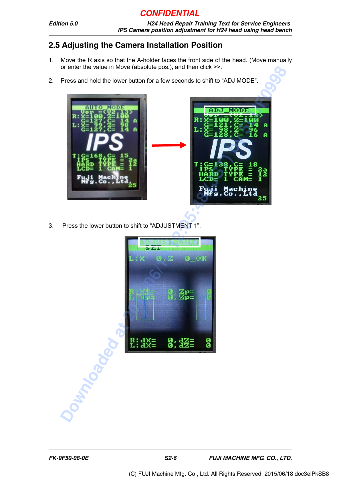
1. Move the R axis so that the A-holder faces the front side of the head. (Move manually
or enter the value in Move (absolute pos.), and then click >>.
2. Press and hold the lower button for a few seconds to shift to “ADJ MODE”.
3. Press the lower button to shift to “ADJUSTMENT 1”.
FK-9F50-08-0E S2-6 FUJI MACHINE MFG. CO., LTD.
CONFIDENTIAL
Downloaded at 2015/06/18 12:05:48 (JST) by 5LUF0998
(C) FUJI Machine Mfg. Co., Ltd. All Rights Reserved. 2015/06/18 doc3elPkSB8
Edition 5.0 H24 Head Repair Training Text for Service Engineers
IPS Camera position adjustment for H24 head using head bench
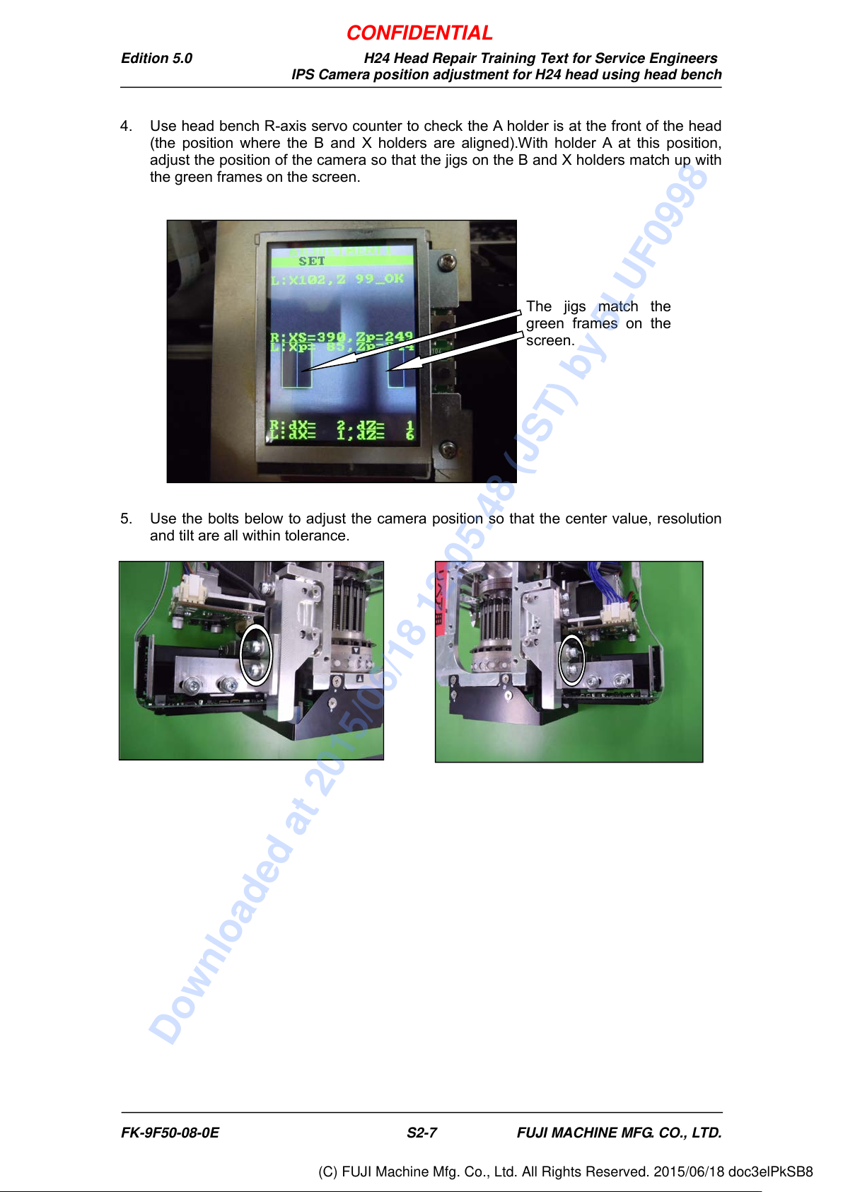
4. Use head bench R-axis servo counter to check the A holder is at the front of the head
(the position where the B and X holders are aligned).With holder A at this position,
adjust the position of the camera so that the jigs on the B and X holders match up with
the green frames on the screen.
5. Use the bolts below to adjust the camera position so that the center value, resolution
and tilt are all within tolerance.
The jigs match the
green frames on the
screen.
FK-9F50-08-0E S2-7 FUJI MACHINE MFG. CO., LTD.
CONFIDENTIAL
Downloaded at 2015/06/18 12:05:48 (JST) by 5LUF0998
(C) FUJI Machine Mfg. Co., Ltd. All Rights Reserved. 2015/06/18 doc3elPkSB8