1_H24维修手册.pdf - 第46页
E d i ti o n 5 .0 H 24 H ead R ep ai r T r ai n i n g T ext f o r S er vi ce E n g i n e e r s R ep l aci n g th e Z - axi s b al l scr ew 8. A t t ac h t he be ar i n g r et ai ne r . 9. T i g ht en t he Z - a xi s b a …
Edition 5.0 H24 Head Repair Training Text for Service Engineers
Replacing the Z-axis ball screw
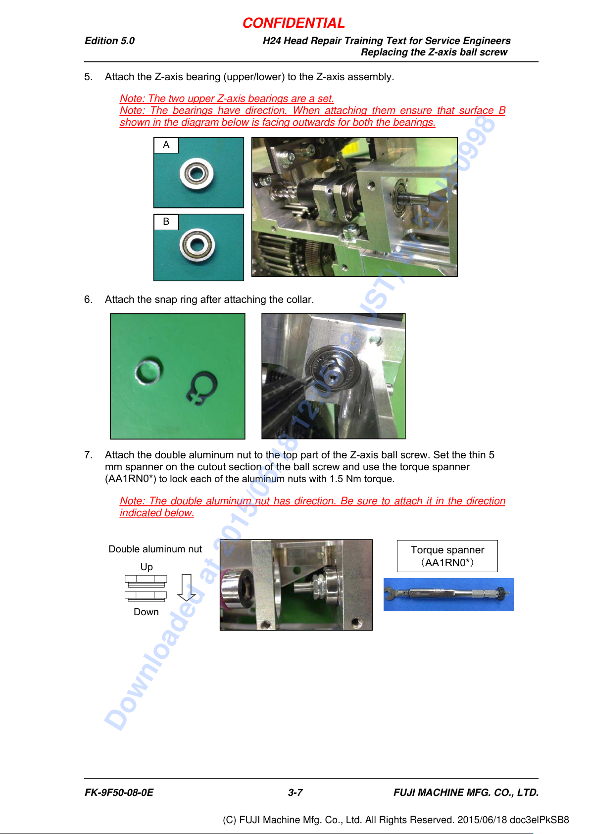
5. Attach the Z-axis bearing (upper/lower) to the Z-axis assembly.
Note: The two upper Z-axis bearings are a set.
Note: The bearings have direction. When attaching them ensure that surface B
shown in the diagram below is facing outwards for both the bearings.
6. Attach the snap ring after attaching the collar.
7. Attach the double aluminum nut to the top part of the Z-axis ball screw. Set the thin 5
mm spanner on the cutout section of the ball screw and use the torque spanner
(AA1RN0*
) to lock each of the aluminum nuts with 1.5 Nm torque.
Note: The double aluminum nut has direction. Be sure to attach it in the direction
indicated below.
B
A
Double aluminum nut
Down
Up
Torque spanner
(AA1RN0*)
FK-9F50-08-0E
3-7
FUJI MACHINE MFG. CO., LTD.
CONFIDENTIAL
Downloaded at 2015/06/18 12:05:48 (JST) by 5LUF0998
(C) FUJI Machine Mfg. Co., Ltd. All Rights Reserved. 2015/06/18 doc3elPkSB8
Edition 5.0 H24 Head Repair Training Text for Service Engineers
Replacing the Z-axis ball screw
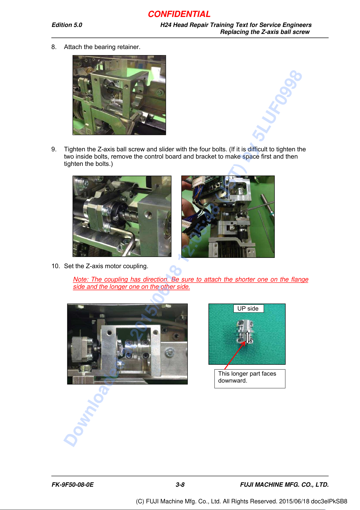
8. Attach the bearing retainer.
9. Tighten the Z-axis ball screw and slider with the four bolts. (If it is difficult to tighten the
two inside bolts, remove the control board and bracket to make space first and then
tighten the bolts.)
10. Set the Z-axis motor coupling.
Note: The coupling has direction. Be sure to attach the shorter one on the flange
side and the longer one on the other side.
This longer part faces
downward.
UP side
FK-9F50-08-0E
3-8
FUJI MACHINE MFG. CO., LTD.
CONFIDENTIAL
Downloaded at 2015/06/18 12:05:48 (JST) by 5LUF0998
(C) FUJI Machine Mfg. Co., Ltd. All Rights Reserved. 2015/06/18 doc3elPkSB8
Edition 5.0 H24 Head Repair Training Text for Service Engineers
Replacing the Z-axis ball screw
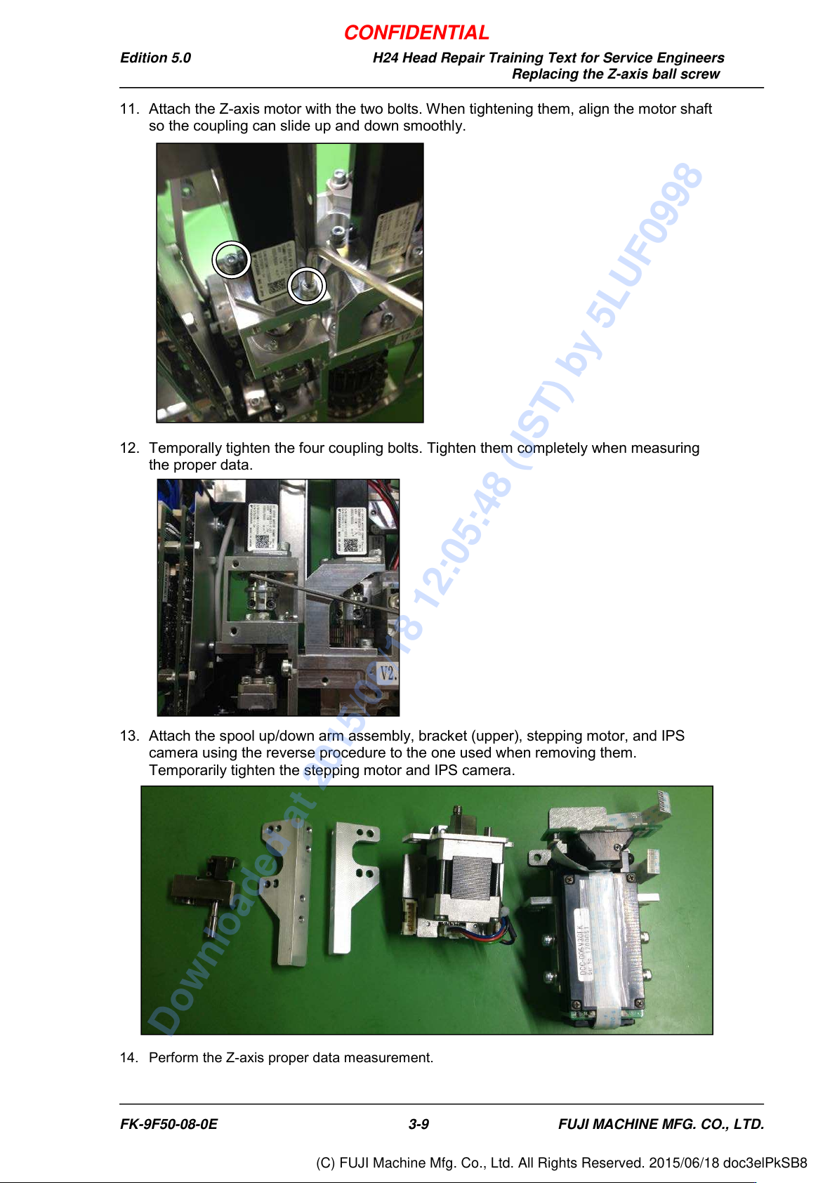
11. Attach the Z-axis motor with the two bolts. When tightening them, align the motor shaft
so the coupling can slide up and down smoothly.
12. Temporally tighten the four coupling bolts. Tighten them completely when measuring
the proper data.
13. Attach the spool up/down arm assembly, bracket (upper), stepping motor, and IPS
camera using the reverse procedure to the one used when removing them.
Temporarily tighten the stepping motor and IPS camera.
14. Perform the Z-axis proper data measurement.
FK-9F50-08-0E
3-9
FUJI MACHINE MFG. CO., LTD.
CONFIDENTIAL
Downloaded at 2015/06/18 12:05:48 (JST) by 5LUF0998
(C) FUJI Machine Mfg. Co., Ltd. All Rights Reserved. 2015/06/18 doc3elPkSB8