1_H24维修手册.pdf - 第69页
Edi t i on 5 .0 H 24 H e ad R e p ai r T r a i n i n g T ext f o r S er vi ce E n g i n eer s A dj us t i n g t h e N o z z l e L o w er i n g L ever C h eck S en so r a nd M ea su r i n g t h e A i r P r essu r e 5. S t…
Edition 5.0
H24 Head Repair Training Text for Service Engineers
Adjusting the Nozzle Lowering Lever Check Sensor and Measuring the Air Pressure
6.1 Nozzle Lowering Lever Check Sensor
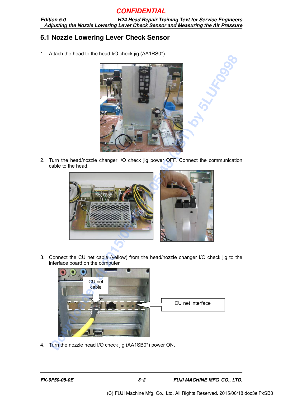
1. Attach the head to the head I/O check jig (AA1RS0*).
2. Turn the head/nozzle changer I/O check jig power OFF. Connect the communication
cable to the head.
3. Connect the CU net cable (yellow) from the head/nozzle changer I/O check jig to the
interface board on the computer.
4. Turn the nozzle head I/O check jig (AA1SB0*) power ON.
CU net interface
CU net
cable
FK-9F50-08-0E
6-2
FUJI MACHINE MFG. CO., LTD.
CONFIDENTIAL
Downloaded at 2015/06/18 12:05:48 (JST) by 5LUF0998
(C) FUJI Machine Mfg. Co., Ltd. All Rights Reserved. 2015/06/18 doc3elPkSB8
Edition 5.0
H24 Head Repair Training Text for Service Engineers
Adjusting the Nozzle Lowering Lever Check Sensor and Measuring the Air Pressure
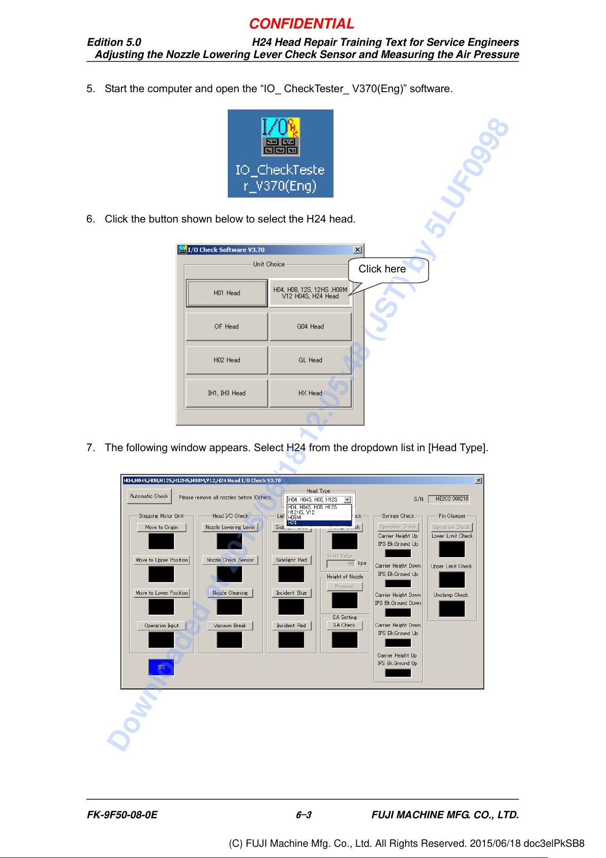
5. Start the computer and open the “IO_ CheckTester_ V370(Eng)” software.
6. Click the button shown below to select the H24 head.
7. The following window appears. Select H24 from the dropdown list in [Head Type].
Click here
FK-9F50-08-0E
6-3
FUJI MACHINE MFG. CO., LTD.
CONFIDENTIAL
Downloaded at 2015/06/18 12:05:48 (JST) by 5LUF0998
(C) FUJI Machine Mfg. Co., Ltd. All Rights Reserved. 2015/06/18 doc3elPkSB8
Edition 5.0
H24 Head Repair Training Text for Service Engineers
Adjusting the Nozzle Lowering Lever Check Sensor and Measuring the Air Pressure
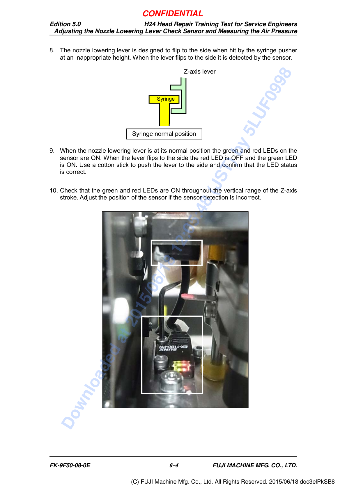
8. The nozzle lowering lever is designed to flip to the side when hit by the syringe pusher
at an inappropriate height. When the lever flips to the side it is detected by the sensor.
9. When the nozzle lowering lever is at its normal position the green and red LEDs on the
sensor are ON. When the lever flips to the side the red LED is OFF and the green LED
is ON. Use a cotton stick to push the lever to the side and confirm that the LED status
is correct.
10. Check that the green and red LEDs are ON throughout the vertical range of the Z-axis
stroke. Adjust the position of the sensor if the sensor detection is incorrect.
Syringe
Syringe normal position
Z-axis lever
FK-9F50-08-0E
6-4
FUJI MACHINE MFG. CO., LTD.
CONFIDENTIAL
Downloaded at 2015/06/18 12:05:48 (JST) by 5LUF0998
(C) FUJI Machine Mfg. Co., Ltd. All Rights Reserved. 2015/06/18 doc3elPkSB8