1_H24维修手册.pdf - 第71页
Edi t i on 5 .0 H 24 H e ad R e p ai r T r a i n i n g T ext f o r S er vi ce E n g i n eer s A dj us t i n g t h e N o z z l e L o w er i n g L ever C h eck S en so r a nd M ea su r i n g t h e A i r P r essu r e 11 . C…
Edition 5.0
H24 Head Repair Training Text for Service Engineers
Adjusting the Nozzle Lowering Lever Check Sensor and Measuring the Air Pressure
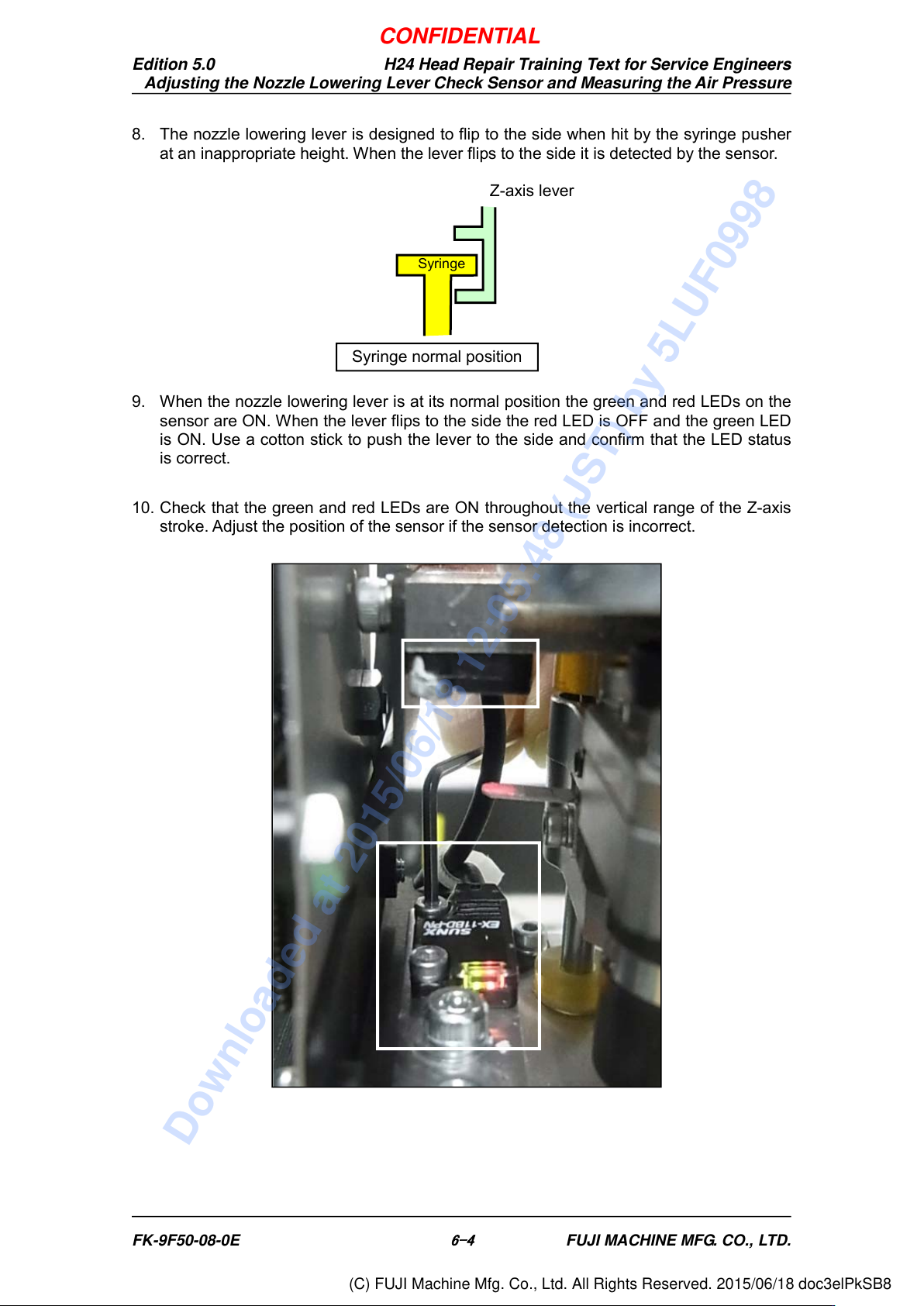
8. The nozzle lowering lever is designed to flip to the side when hit by the syringe pusher
at an inappropriate height. When the lever flips to the side it is detected by the sensor.
9. When the nozzle lowering lever is at its normal position the green and red LEDs on the
sensor are ON. When the lever flips to the side the red LED is OFF and the green LED
is ON. Use a cotton stick to push the lever to the side and confirm that the LED status
is correct.
10. Check that the green and red LEDs are ON throughout the vertical range of the Z-axis
stroke. Adjust the position of the sensor if the sensor detection is incorrect.
Syringe
Syringe normal position
Z-axis lever
FK-9F50-08-0E
6-4
FUJI MACHINE MFG. CO., LTD.
CONFIDENTIAL
Downloaded at 2015/06/18 12:05:48 (JST) by 5LUF0998
(C) FUJI Machine Mfg. Co., Ltd. All Rights Reserved. 2015/06/18 doc3elPkSB8
Edition 5.0
H24 Head Repair Training Text for Service Engineers
Adjusting the Nozzle Lowering Lever Check Sensor and Measuring the Air Pressure
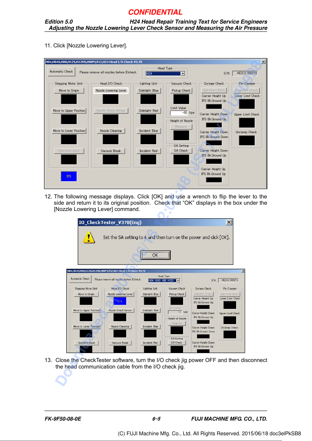
11. Click [Nozzle Lowering Lever].
12. The following message displays. Click [OK] and use a wrench to flip the lever to the
side and return it to its original position. Check that “OK” displays in the box under the
[Nozzle Lowering Lever] command.
13. Close the CheckTester software, turn the I/O check jig power OFF and then disconnect
the head communication cable from the I/O check jig.
FK-9F50-08-0E
6-5
FUJI MACHINE MFG. CO., LTD.
CONFIDENTIAL
Downloaded at 2015/06/18 12:05:48 (JST) by 5LUF0998
(C) FUJI Machine Mfg. Co., Ltd. All Rights Reserved. 2015/06/18 doc3elPkSB8
Edition 5.0
H24 Head Repair Training Text for Service Engineers
Adjusting the Nozzle Lowering Lever Check Sensor and Measuring the Air Pressure
6.2 Vacuum Break Pressure Measurement
Head Air Pressure Table
Caution: The values in the table apply to new heads and should only be
used as a reference for used heads.
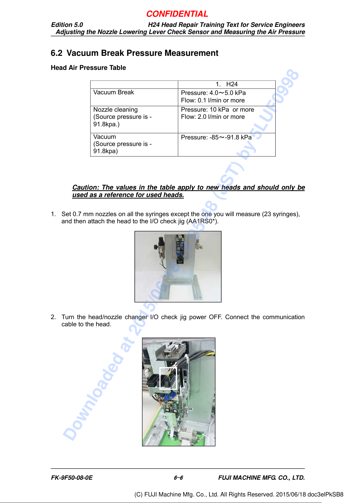
1. Set 0.7 mm nozzles on all the syringes except the one you will measure (23 syringes),
and then attach the head to the I/O check jig (AA1RS0*).
2. Turn the head/nozzle changer I/O check jig power OFF. Connect the communication
cable to the head.
1. H24
Vacuum Break
Pressure: 4.0
~
5.0 kPa
Flow: 0.1 l/min or more
Nozzle cleaning
(Source pressure is -
91.8kpa.)
Pressure: 10 kPa or more
Flow: 2.0 l/min or more
Vacuum
(Source pressure is -
91.8kpa)
Pressure: -85
~
-91.8 kPa
FK-9F50-08-0E
6-6
FUJI MACHINE MFG. CO., LTD.
CONFIDENTIAL
Downloaded at 2015/06/18 12:05:48 (JST) by 5LUF0998
(C) FUJI Machine Mfg. Co., Ltd. All Rights Reserved. 2015/06/18 doc3elPkSB8