4M184002w_F8S.pdf - 第306页
4OM-1840 5-1-7 1604-001 Sprocket Dirt and/or Component Adhesion Suppressor Lifting, Deformation, and/or Component Adhesion on Inner Side Front Hook Deformation Cover T ape T ake-Up Gear Dirt and/or Component Adhesion Cle…
4OM-1840
5-1-61604-001
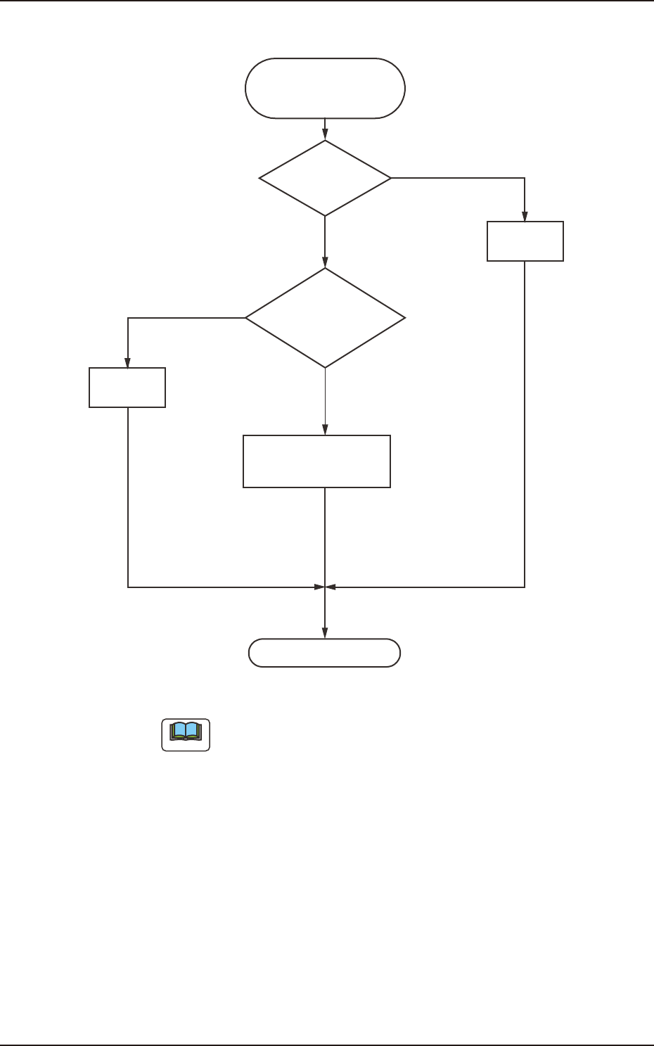
(2) Frequent Pickup Errors on Specic Feeder Slot No.
Frequent Pick-Up Errors
on Specific Feeder Slot No.
Operation Check
Correction
OK
NG
Note (b)
OK
OK
NG
Note (a)
Feeder Check
Collation
with Component
Library Data
Verification of Feeder (B)
Offset Data
Adjustment
F4E4
Note
(a) See Figs. 4E5 and 4E6 on the next page for the checkpoints on tape
feeders.
program change operation because it is prepared for the previous
components.
2.2 Symptom-Based Troubleshooting
4OM-1840
5-1-71604-001
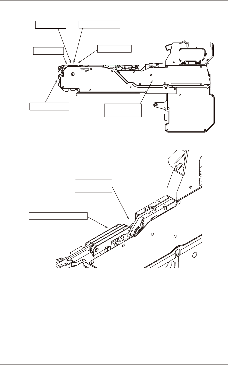
Sprocket
Dirt and/or
Component Adhesion
Suppressor
Lifting, Deformation,
and/or Component
Adhesion on
Inner Side
Front Hook
Deformation
Cover Tape
Take-Up Gear
Dirt and/or
Component Adhesion
Clearance, Deformation,
and/or Dirt
Pickup Position
Peeling Area
Positioning and/or
Elimination of Positional Deviation
F4E5
Cover Tape
Take-Up Gear
Dirt and/or
Component Adhesion
Threading of Cover Tape
This should be mounted
correctly.
F4E6
2.2 Symptom-Based Troubleshooting
4OM-1840
5-1-81604-001
3. Troubleshooting on Placement Errors
3.1 Cause and Remedy of Placement Errors
(1) Positional and Angular Deviations of Component Placement
(1-1) Situational Grasp of Error Generation
Positional and angular deviations may be generated in either Process C or D
and E.
See Fig. 4E1.
By placing a component on the PCB where a double-faced adhesive tape is
angular deviations are generated.
When a positional deviation is generated on the double-faced tape, it
indicates that positional and angular deviations occur in Process C.
When no positional deviation is generated, it means that positional and
angular deviations occur in Process D or E.
(1-2) Positional and Angular Deviations in Process C
When a positional deviation is generated due to the movement of the head
after component recognition or a rotational deviation by placement angle
correction, the deviation may be caused mainly by the following two factors.
•
Deterioration of Vacuum Suction Force
•
Vibration or Shock during Nozzle (Head) Movement
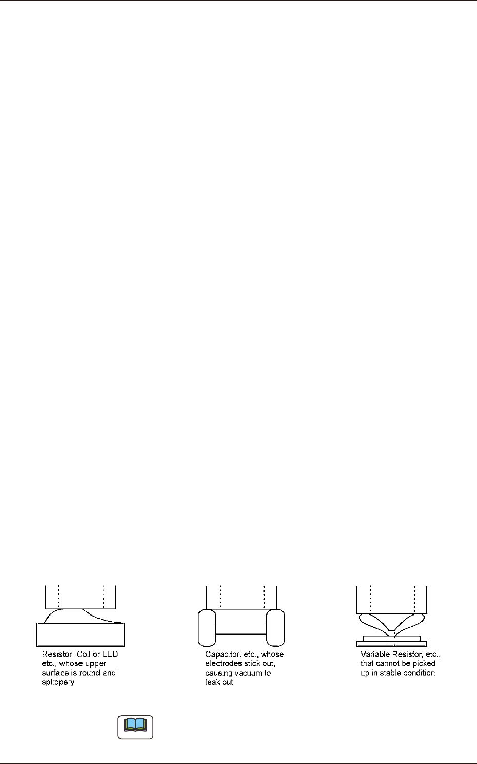
When one of the above factors exists, unstable components (components that
cannot be picked up in stable condition) such as those shown in F4E7 are
When a positional deviation is generated on the components (the components
of the same type that have been used in the past actual production), check for
the above-described factors.
As for vacuum suction force, check the nozzle and the vacuum line.
As for vibration during nozzle movement, check the related spots in the
range of Process C.
Easily-Dislocated Components during Placement (Example 1) F4E7
Note
When there is a protruding portion on the upper surface of a component,
the lower surface of the vacuum nozzle may be worn out, causing an error
during the teaching operation through component recognition lighting.
3. Troubleshooting on Placement Errors