4M184002w_F8S.pdf - 第89页
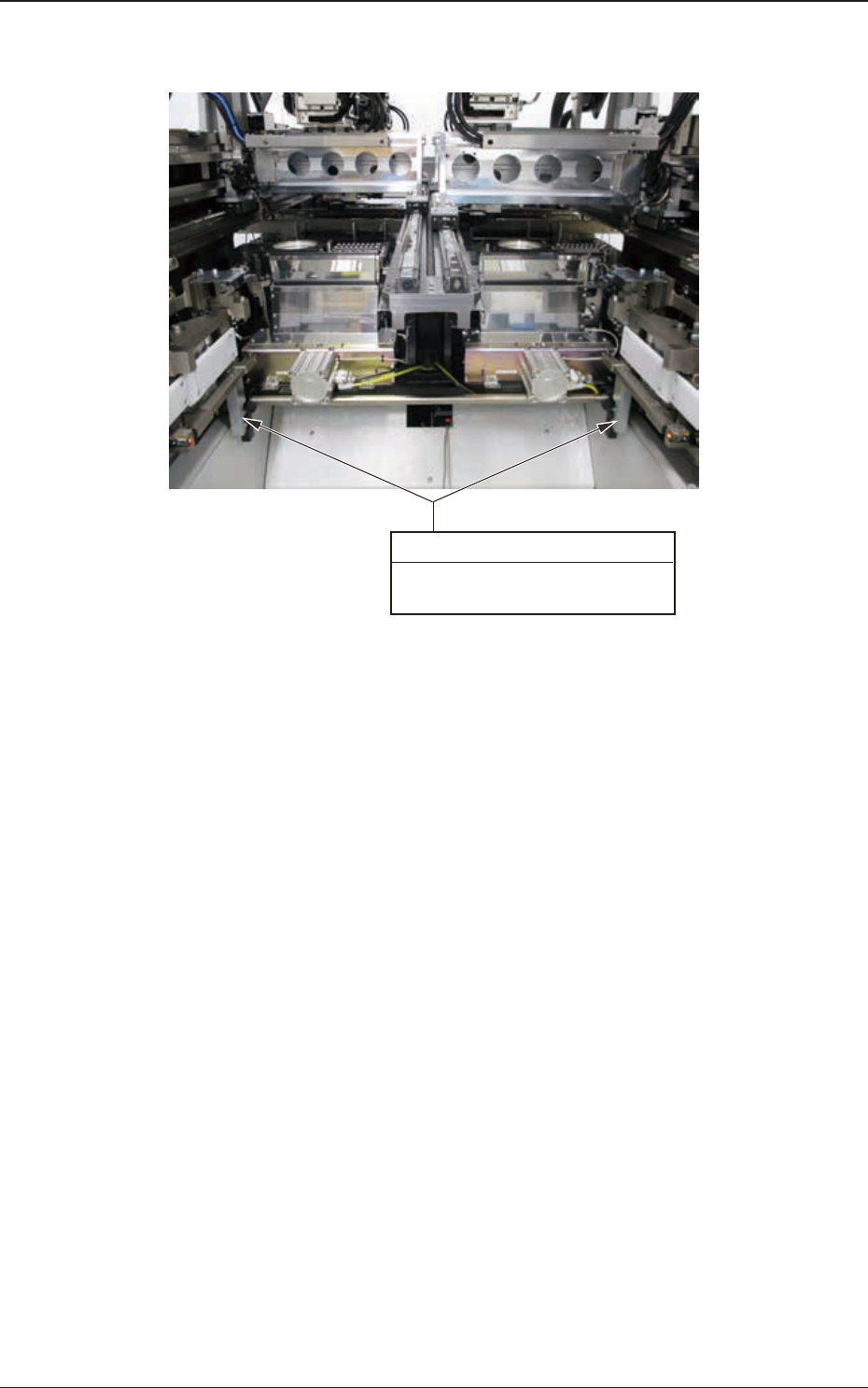
4OM-1840 1-4-14 1604-001 4.4 Feeder Base Driving Section Worm Gear (2 locations) Every 3 Months Lubrications Required T ime : 2 minutes Fig. 4A4-17 4.4 Feeder Base Driving Section
4OM-1840
1-4-131604-001
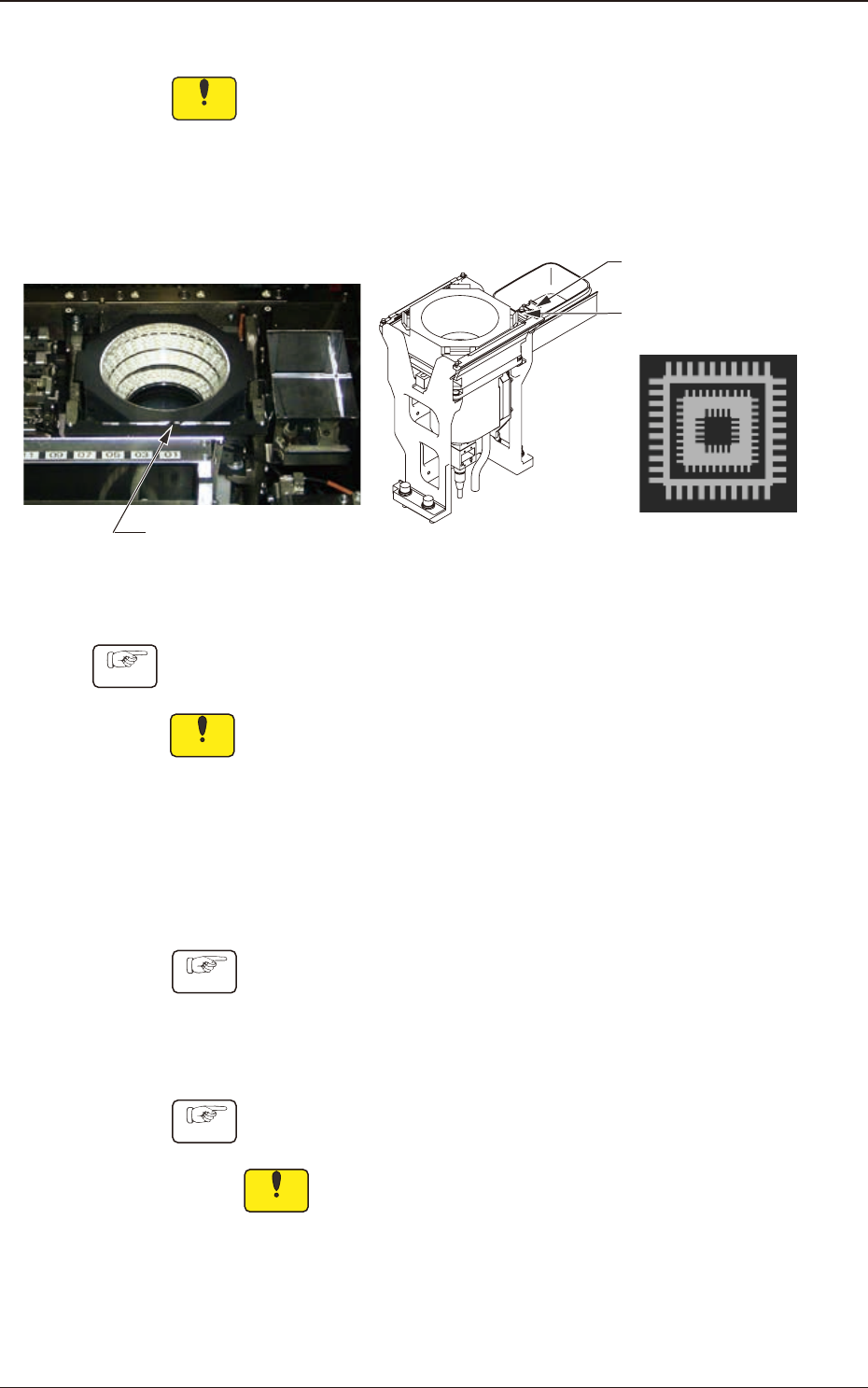
4.3.3 Fiducial Mark (Four Locations) Cleaning
Notice
Use a suction force (of a vacuum cleaner) for the cleaning.
Do not blow air to any cleaning section with an air gun.
When the air is blown, dirt or dust inside the machine will disperse,
causing a malfunction in the recognition or machine operation.
Cycle : Every Week (Required Time : 2 minutes)
Fiducial Marks
Teaching Plates
(2 locations)
QFP Glass Plate Jigs
(2 pcs.)
Fig. 4A4-16
Procedure
Notice
(a) Sebum (ngerprint) or oil should not adhere to the ducial marks.
If sebum or oil adheres, wipe it o with a lens cleaning cloth which
contains a small amount of alcohol.
(b) Because the ducial mark is on a coating lm, handle it carefully not
to damage.
•
Teaching Plates (2 locations)
Cycle : Every Month (Required : 1 minute)
Procedure
and dust with a rag.
•
QFP Glass Plate Jigs JG-0335, KYA-M3804-000 (2 pcs.)
Cycle : Every Month (Required : 1 minute)
Procedure
Wipe the jigs with a dry lens cleaning cloth.
Notice
Sebum (ngerprint) or oil should not adhere to the QFP glass
plate jigs. If sebum or oil adheres, wipe it o with a lens cleaning
cloth which contains a small amount of alcohol.
4.3 Component Recognition Camera Section
4OM-1840
1-4-141604-001
4.4 Feeder Base Driving Section
Worm Gear (2 locations)
Every 3 Months Lubrications
Required Time : 2 minutes
Fig. 4A4-17
4.4 Feeder Base Driving Section
4OM-1840
1-4-151604-001
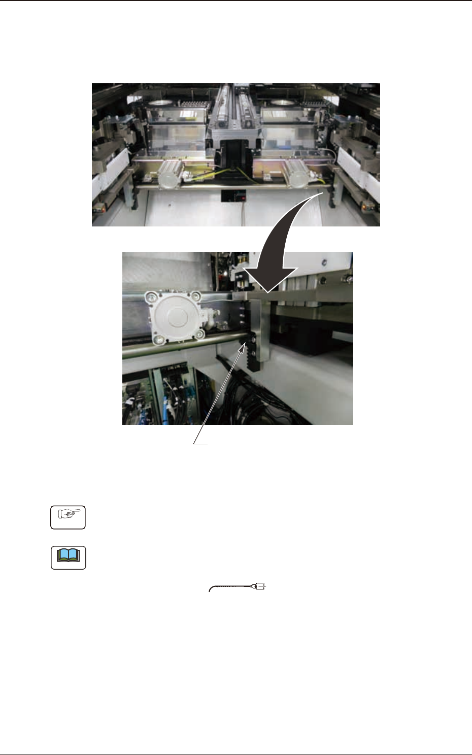
4.4.1 Warm Gear (Two Locations) Oiling
Cycle : Every 3 Months (Required Time : 2 minutes)
Grease : MOLYNOC GREASE AP1
Worm Gear
Fig. 4A4-18
Procedure
Apply a small amount of new grease to the worm gears with a syringe.
Note
Use No. 19 (brown) nozzle.
No.19
Fig. 4A4-19
4.4 Feeder Base Driving Section