SIPLACE Station Software 7xx to 714 介绍.pdf - 第107页
Station Software 7xx to 714.0 (R20-2) / Feature Description 11/2020 Edition 107 Example In the following example th e pick-up angle is adjusted simultaneousl y with the problem situation in Figure 7- 36 ( Settings mismat…
Station Software 7xx to 714.0 (R20-2) / Feature Description 11/2020 Edition
106
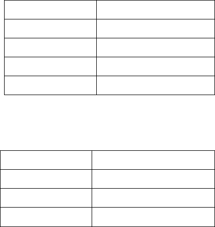
Dependent on the pick-up position, the following default pitch values are valid.
For 8mm X feeders:
Pick-up position
Default pitch
1
2 mm
2
4 mm
3
4 mm
4
8 mm
For 2x8mm X feeders:
Pick-up position
Default pitch
1
2 mm
2
4 mm
3
8 mm
Priorities in the Display
If multiple problem situations occur simultaneously, the warning or the state text of the situation
with the highest priority will be displayed in the Details view of the feeder. The following
precedence is valid (descending priority):
– Pick-up angle has been changed (with warning/icon)
– Pitch to small (with warning/icon)
– Settings mismatch (for handling option 1 only, with warning/icon)
– Pick-up position has been changed (without warning/icon)
If the current displayed problem case is solved first things first, the message for the next subjacent
priority level will be visible.
Station Software 7xx to 714.0 (R20-2) / Feature Description 11/2020 Edition
107
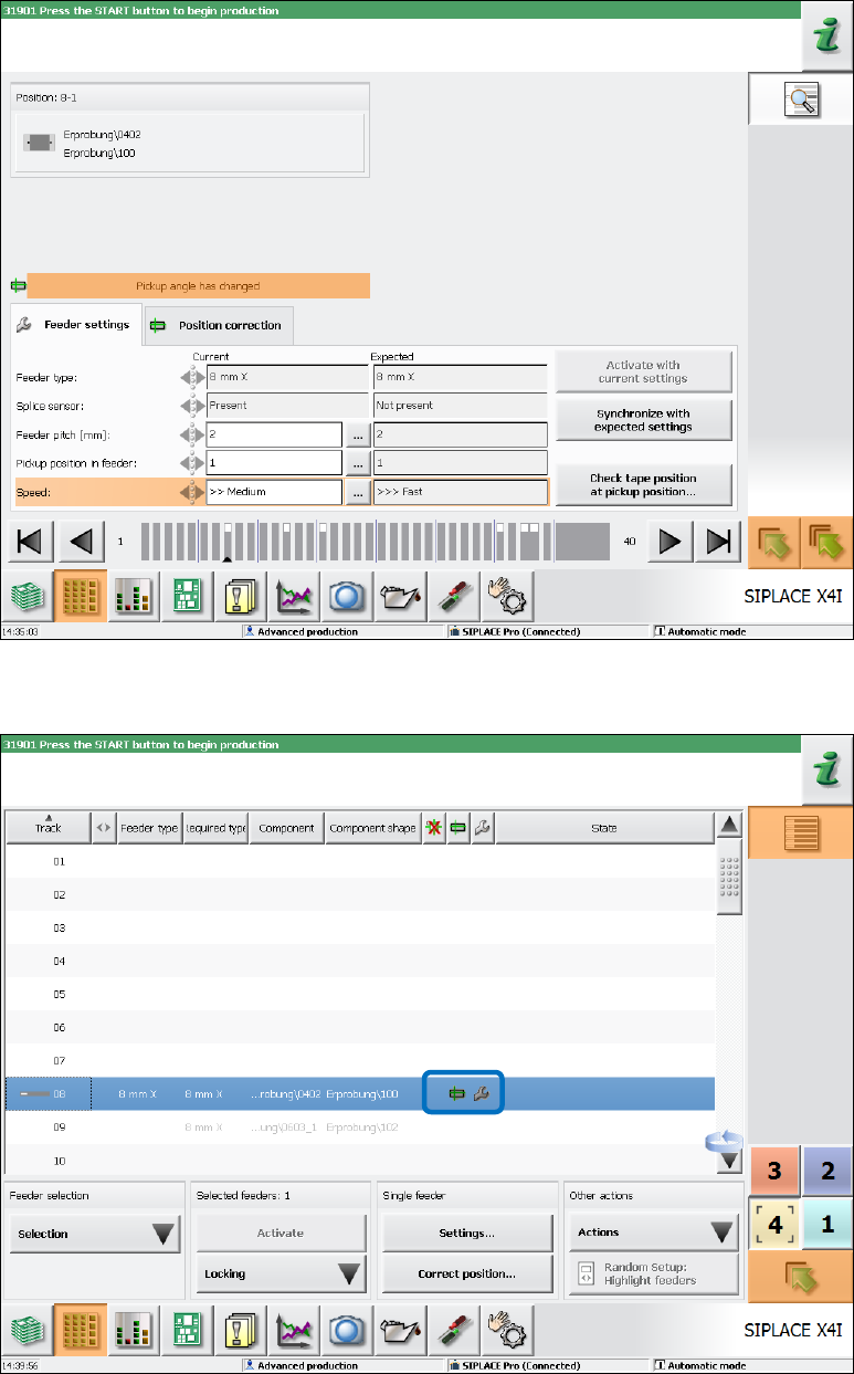
Example
In the following example the pick-up angle is adjusted simultaneously with the problem situation in
Figure 7-36 (Settings mismatch, because the speed was changed). Thus, the Pickup angle has
changed warning is activated and the warning text for the mismatching settings is overlain.
Figure 7-37: Changed pick-up angle
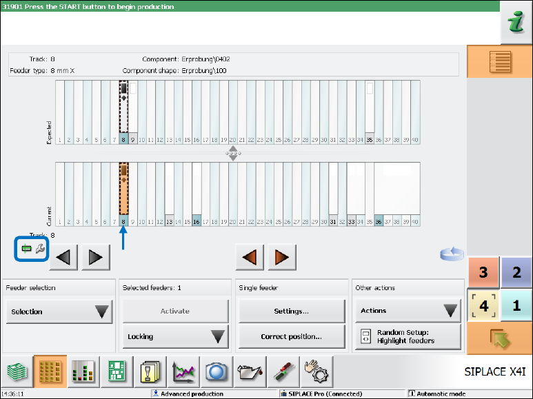
In the setup view of the locations, the icons are displayed for both problem situations.
Figure 7-38: Warning icons in setup view
Station Software 7xx to 714.0 (R20-2) / Feature Description 11/2020 Edition
108
In the setup overview, the icons are displayed for both problem situations and the concerned track
is additionally highlighted in orange.
Figure 7-39: Setup overview
7.38.6 Limited Correction Area for the Pick-up Position
Compatible mode: Complete
To avoid that components are picked up from an incorrect position, the allowed correction area has
been limited on the Basic production and Advanced Production activity levels.
The maximum offset that can be set during teaching is derived from the following information:
– Specific component length and width measurements that are defined in the component shape.
– The 50% percentage factor that is stored in the software configuration and is used for all
component and feeder types.
The allowed offset then comes out in the direction of the component length as +/- component
length * percentage factor, in the direction of the component width as +/- component
width * percentage factor.
I.e., for a component with a length of 6mm and a width of 4mm and percentage factor 50%, the
pick-up position may be changed by 3mm und 2mm respectively in the corresponding directions.