SIPLACE Station Software 7xx to 714 介绍.pdf - 第114页
Station Software 7xx to 714.0 (R20-2) / Feature Description 11/2020 Edition 114 7.39 Fault-Tolerant Operation of Twin Head Compatible mode: Complete Until now, the entire machine could not produce anymore if one T win He…
Station Software 7xx to 714.0 (R20-2) / Feature Description 11/2020 Edition
113
Changing the pick-up position will have the following consequences:
– The changed setting is transmitted to the feeder that then presents the component at the new
defined position. To see the changed position, the operator must restart the Check tape
position at pickup position dialog.
– If uploading is allowed, the changed pick-up position settings are immediately uploaded to
SIPLACE Pro into the local setup data.
After the feeder has been stepped with the Feed forward button, a new camera image of the pick-
up position will be automatically displayed. If necessary, the pick-up position must be re-taught in
the Position correction dialog.
7.38.9 Tape Pocket Detection of Component Shape 0603
Compatible mode: Complete
The tape pockets of component shape 0603 have been integrated in the default workflow of the
tape pocket detection. In connection with this change, the behavior in error cases has been
modified, too. After a pocket detection error has occurred, the software still tries to pick up the
component. If the component cannot be picked up, the machine stops with a vacuum error.
Additionally, the Check and teach feeder pocket shapes button is highlighted in red. If this button
is selected, a dialog is opened in which the tape pocket detection can be performed manually or be
skipped.
Station Software 7xx to 714.0 (R20-2) / Feature Description 11/2020 Edition
114
7.39 Fault-Tolerant Operation of Twin Head
Compatible mode: Complete
Until now, the entire machine could not produce anymore if one Twin Head segment failed,
because no reference run could be performed for the concerned segment after machine start.
Usually, this caused a complete line downtime in the production.
As of this station software version it is possible to deactivate the concerned Twin Head segment or
remove it from the configuration via the software.
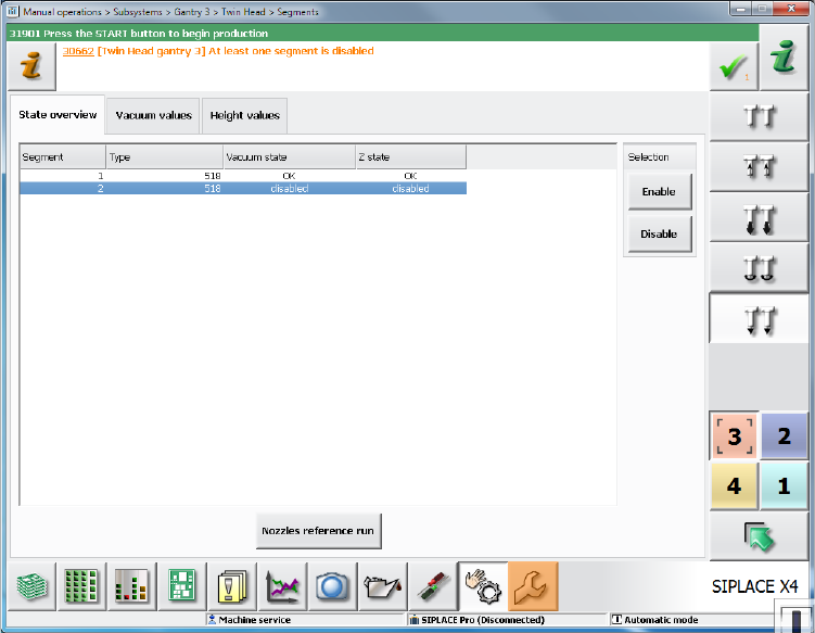
With the Deactivate Segment option, the segment is not used during placement. However,
communication via CAN bus is possible and single actions can be performed with the segment,
e.g. securing the z-axis. This option corresponds to the method with which segments of the CPP
and C&P20 placement heads are deactivated and can be set during running operation under
Manual operations on the Machine service activity level.
Figure 7-46: Manual operations – deactivating segment
If both segments are deactivated but placement content is defined for the Twin Head, the machine
stops when the board enters and the Cannot continue production error message will be
displayed.
Station Software 7xx to 714.0 (R20-2) / Feature Description 11/2020 Edition
115
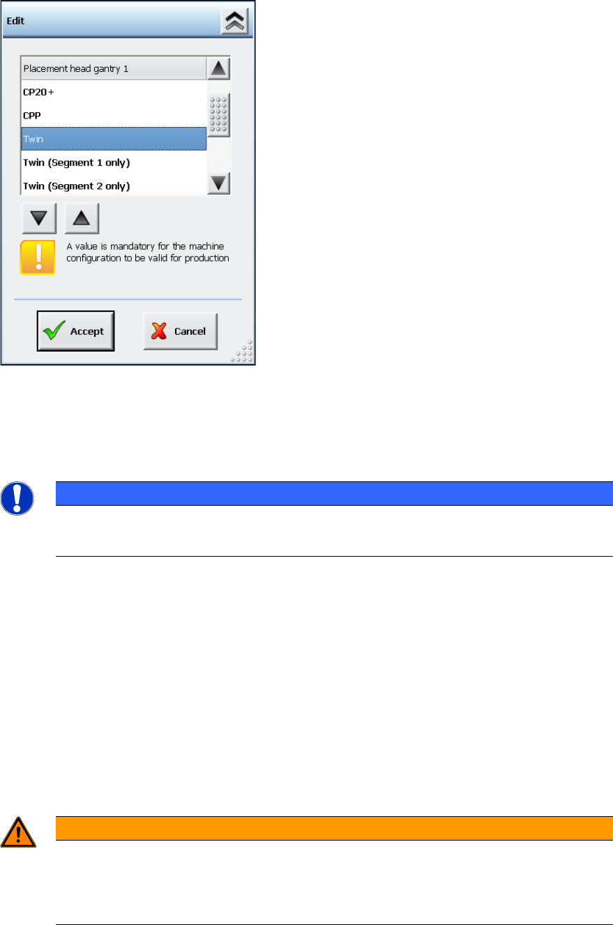
With the Remove Segment from configuration option the segment is disconnected from CAN
bus and power supply and no communication is possible. This option can be selected in the Auto
Configuration under Service – Machine configuration on the Machine service activity level.
Figure 7-47: Machine configuration – Removing segment from configuration
As an additional option to Twin, it is possible to select either Twin (Segment 1 only) or Twin
(Segment 2 only).
The calibration steps are performed for the active segment only.
NOTICE
Head Calibration and Head Mapping
The head calibration and head mapping are only possible if Segment 1 is active!
Download of the embedded software is not provided for a segment that has been removed from the
configuration.
If Segment 1 has been deactivated or removed from the configuration, e.g. some single placement
positions might not be reachable because of the limited traveling range of Segment 2. In this case,
the machine stops with a corresponding error message and the board cannot be finished.
However, the placement position or the feeder can be omitted as usual.
If the head option in the Auto Configuration differs from the configured head option (Twin, Twin
(Segment 1 only) or Twin (Segment 2 only)), a corresponding message is displayed. The
inconsistency between the last and the current configuration is displayed in the Machine
configuration.
After the Twin Head configuration has been changed, the station software is rebooted
automatically.
WARNING
Do not dismantle a segment that is defect or has been removed from the
configuration!
A segment that is defect or has been removed from the configuration must not be
dismantled, as this might have negative effects on the gantry dynamics.