SIPLACE Station Software 7xx to 714 介绍.pdf - 第116页
Station Software 7xx to 714.0 (R20-2) / Feature Description 11/2020 Edition 116 Restrictions – If Segment 1 has been dea ctivated or removed from t he configuration, e.g. some single placement positions might not be reac…
Station Software 7xx to 714.0 (R20-2) / Feature Description 11/2020 Edition
115
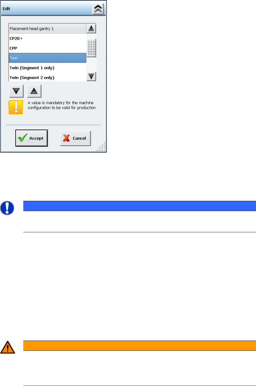
With the Remove Segment from configuration option the segment is disconnected from CAN
bus and power supply and no communication is possible. This option can be selected in the Auto
Configuration under Service – Machine configuration on the Machine service activity level.
Figure 7-47: Machine configuration – Removing segment from configuration
As an additional option to Twin, it is possible to select either Twin (Segment 1 only) or Twin
(Segment 2 only).
The calibration steps are performed for the active segment only.
NOTICE
Head Calibration and Head Mapping
The head calibration and head mapping are only possible if Segment 1 is active!
Download of the embedded software is not provided for a segment that has been removed from the
configuration.
If Segment 1 has been deactivated or removed from the configuration, e.g. some single placement
positions might not be reachable because of the limited traveling range of Segment 2. In this case,
the machine stops with a corresponding error message and the board cannot be finished.
However, the placement position or the feeder can be omitted as usual.
If the head option in the Auto Configuration differs from the configured head option (Twin, Twin
(Segment 1 only) or Twin (Segment 2 only)), a corresponding message is displayed. The
inconsistency between the last and the current configuration is displayed in the Machine
configuration.
After the Twin Head configuration has been changed, the station software is rebooted
automatically.
WARNING
Do not dismantle a segment that is defect or has been removed from the
configuration!
A segment that is defect or has been removed from the configuration must not be
dismantled, as this might have negative effects on the gantry dynamics.
Station Software 7xx to 714.0 (R20-2) / Feature Description 11/2020 Edition
116
Restrictions
– If Segment 1 has been deactivated or removed from the configuration, e.g. some single
placement positions might not be reachable because of the limited traveling range of Segment
2. The machine stops with a corresponding error message and the board cannot be finished.
No plausibility check will be performed in advance for a defined job or a board that enters the
machine.
– Head calibration is not possible, if Segment 1 is deactivated or has been removed from the
configuration. If this is necessary, the functioning segment must be installed on the position of
Segment 1.
– No CAN communication with a segment that has been removed from the configuration.
– No control of the Z-security for a segment that has been removed from the configuration.
– A segment that has been removed from the configuration will not be actively secured but will
generally be hold by the cylinder. The segment is held high enough, so that it will not come in
touch with placed components. If necessary, the nozzle must be removed manually.
– If a long/wide component is placed by the active segment, no check will be performed whether
a component is wiped off from the segment that has been removed from the configuration.
7.40 Error Message "Narrow edges on the encoder's track signals"
Compatible mode: Complete
The 30463 Encoder error: Narrow edges on the encoder's track signals error
message for placement machines with H-gantries (SX1/SX2 and DX1/DX2) has been modified so
that the error can be rapidly found.
The fixed bearing or floating bearing sides and the gantry number are additionally displayed in the
error message.
7.41 Automatic Backspacing to Lower Activity Level
Compatible mode: Complete
If the GUI stands in the Production view and no entries are made within a preset time, the software
automatically switches into the Basic production activity level. This is performed regardless of
which activity level was active before.
The backspacing and the time interval can be modified under Settings – GUI settings. Default: the
function is enabled.
7.42 SIPLACE LED Pairing
Compatible mode: Complete
SIPLACE LED Pairing supports the programming process when LEDs are used in electronic
assemblies.
In the *.LRX format the brightness class is added to the component name (in brackets) and usually
consists of 2 characters and in rare cases of 6 characters. The *.LRX2 format does not contain any
brightness class suffixes. Instead of that, a real component with an item number of its own is used
for each brightness class.
The brightness class / brightness class specific components are displayed in the Setup and Filling
level views on the GUI of the station software.
Station Software 7xx to 714.0 (R20-2) / Feature Description 11/2020 Edition
117
7.43 PCB Barcode Detection with Molex Traceability Pad
Compatible mode: Complete
If the barcode is not contained on the board, it may be put onto the board with help of the Molex
Traceability Pad (Molex item no.: [91658-0020]).
The Traceability is packaged in tape reels and can be placed in the first placement area of the first
machine in the line, if it is defined as a component.
Procedure in SIPLACE Pro
The barcode fiducial and the placement position of the Traceability-Pad must be defined in the
same panel. Furthermore, the name of the barcode fiducial must begin with the character string
FOC_Pos, in which Pos is the name of the placement position.
Example
If the placement position name is Pos_23, the name of the appropriate barcode fiducial must
be FOC_Pos_23 or FOC_Pos_23_xyz. So, the station software will not read the FOC_Pos_23
barcode fiducial until the Pos_23 Traceability Pad has been placed.
The barcode will then be treated as if it was already read when the board entered the line. The
Whispering down the Line function is supported.
The Traceability Pad should be placed / read in the placement area 1 of the first placement
machine. Only in this case it is warranted that the Traceability information can be correctly saved
for all stations in the line.
NOTICE
Component Height
Barcodes can only be reliably measured by SIPLACE Vision if the component height
(without board warpage) at the position of the Traceability-Pad is < 1,5mm.
The function can also be used to put a component highly accurately on another component (chip
stacking): for this, the lower component must be equipped with a fiducial that is defined as local
component fiducial, with the nomenclature FOC_BeName for the fiducial name in SIPLACE Pro. By
this name, the software detects that this fiducial shall not be measured until the component has
been placed. The upper component will then be placed relatively to the fiducial. Please also refer to
section 9.3.
Restrictions
– Barcode-controlled production is not supported.
– Traceability is not possible until the barcode has been successfully read. Therefore, the
Traceability Pad should be placed / read in placement area 1 of the first placement machine in
the line. Only in this case, it is warranted that the Traceability information can be correctly
saved for all stations in the line.
– No plausibility check if the placement position is too close to a component.
– Barcodes can only be reliably measured by SIPLACE Vision if the component height (without
board warpage) at the position of the Traceability-Pad is < 1,5mm.
– When the placement position is taught, the barcode / fiducial position will not be moved
correspondingly.