SIPLACE Station Software 7xx to 714 介绍.pdf - 第125页
Station Software 7xx to 714.0 (R20-2) / Feature Description 11/2020 Edition 125 In the Production main view the W afer Feeder is indicated by the icon. Figure 8-1: Production main v iew In the setup overview the Setup vi…

Station Software 7xx to 714.0 (R20-2) / Feature Description 11/2020 Edition
124
8 Feature Description – Station Software V707.x
Features (V707.0)
8.1 SIPLACE CA Series Placement Machines
As of this version the station software supports a new SIPLACE CA4 placement machine model of
the CA-series (Chip Assembly). Additionally, the new SIPLACE CA4 eWLP (embedded Wafer
Level Process) placement machine is supported by the station software. However, this machine
type will not be released for series production in this version.
NOTICE
The CA-machines available in the field do not meet with the required hardware
prerequisites and will not be migrated to station software 707. However, the CA-series
placement machines are still available with the 60x station software.
The new CA-series placement machines mainly differ from the previous CA-machines by the
following features:
– Placement heads with a high-resolution star axis are used to achieve high accuracy. For this,
the new C&P20 M placement head type has been introduced. In SIPLACE Pro this placement
head is referred to as C&P20 M 1xxx.
– Support of WLFO – Wafer Level Fan-Out on the SIPLACE CA4 eWLP placement machine as a
customer project (no release for series production).
The SIPLACE Wafer Systems 12 1&3 and 12 2&4 may be used for the placement of bare dies on
the CA-series placement machines. The communication between station software and the
SIPLACE Wafer Systems runs via the new Wafer Feeder feeder type.
Dip modules may also be used on the SIPLACE Wafer Systems.
Station Software 7xx to 714.0 (R20-2) / Feature Description 11/2020 Edition
125
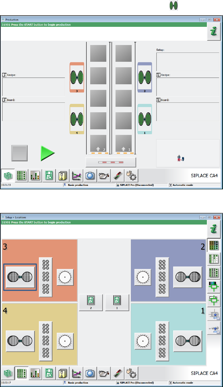
In the Production main view the Wafer Feeder is indicated by the icon.
Figure 8-1: Production main view
In the setup overview the Setup view of the Wafer Feeder may be selected via this icon.
Figure 8-2: Setup overview
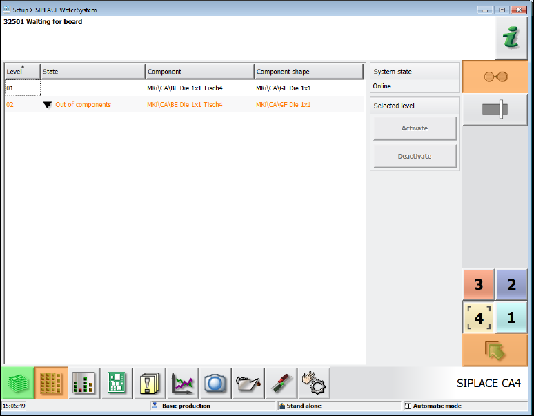
The level numbers, component names and component shapes from the SIPLACE Pro definition
and, if applicable, the error status of the levels are displayed in table form in this view.
Station Software 7xx to 714.0 (R20-2) / Feature Description 11/2020 Edition
126
Figure 8-3: Setup view – Wafer Feeder
8.1.1 Individual Pick-Up Positions for Flip-Chip Nozzles
On the SIPLACE Wafer Systems there is an individual pick-up position for each of the two Flip-
Chip nozzles that must be taught manually. For this, the Machine Service activity level is required.
After the appropriate gantry has been selected three handover positions of the Wafer Feeder
nozzles are displayed under Service – Teaching machine positions on the station software GUI:
2x FlipChip and 1x DieAttach. Dependent on the hardware configuration, either both FlipChip
positions or the single DieAttach position must be taught. Mixed FlipChip and DieAttach operation
is not possible.
The nozzle handover positions may be selected and corrected individually in the Change selected
position tab.
The pick-up position is stored persistently at the station, i.e. it remains after a machine reboot or a
new job download.
8.2 SIPLACE X2 S Placement Machine
The station software supports the new SIPLACE X2 S placement machine of SIPLACE X-series S.
The SIPLACE X2 S has two gantries and supports essentially the same configuration variants and
options as the SIPLACE X3 S with the following exception:
– Smart Pin Support is not supported.