SIPLACE Station Software 7xx to 714 介绍.pdf - 第127页
Station Software 7xx to 714.0 (R20-2) / Feature Description 11/2020 Edition 127 8.3 SIPLACE X4 S micron Placement Ma chine The station software supp orts the new SIPLACE X4 S micron pla cement machine that is ba sed on t…
Station Software 7xx to 714.0 (R20-2) / Feature Description 11/2020 Edition
126
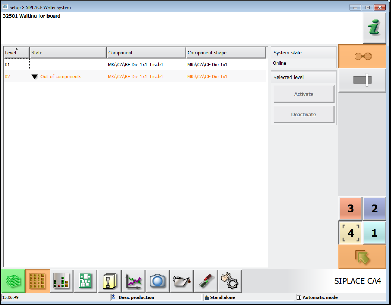
Figure 8-3: Setup view – Wafer Feeder
8.1.1 Individual Pick-Up Positions for Flip-Chip Nozzles
On the SIPLACE Wafer Systems there is an individual pick-up position for each of the two Flip-
Chip nozzles that must be taught manually. For this, the Machine Service activity level is required.
After the appropriate gantry has been selected three handover positions of the Wafer Feeder
nozzles are displayed under Service – Teaching machine positions on the station software GUI:
2x FlipChip and 1x DieAttach. Dependent on the hardware configuration, either both FlipChip
positions or the single DieAttach position must be taught. Mixed FlipChip and DieAttach operation
is not possible.
The nozzle handover positions may be selected and corrected individually in the Change selected
position tab.
The pick-up position is stored persistently at the station, i.e. it remains after a machine reboot or a
new job download.
8.2 SIPLACE X2 S Placement Machine
The station software supports the new SIPLACE X2 S placement machine of SIPLACE X-series S.
The SIPLACE X2 S has two gantries and supports essentially the same configuration variants and
options as the SIPLACE X3 S with the following exception:
– Smart Pin Support is not supported.
Station Software 7xx to 714.0 (R20-2) / Feature Description 11/2020 Edition
127
8.3 SIPLACE X4 S micron Placement Machine
The station software supports the new SIPLACE X4 S micron placement machine that is based on
the SIPLACE X4 S machine type. SIPLACE X4 S micron achieves high accuracy through high-
resolution measurements at the main axes and optimized accuracy of the travel parameters.
The SIPLACE X4 S micron supports essentially the same configuration variants and options as the
SIPLACE X4 S except for the head configuration:
– The SIPLACE X4 S micron is exclusively equipped with the high-precision C&P20 M placement
heads (4x) and the SST 41 component camera type.
8.4 SIPLACE X4i S micron Placement Machine
The station software supports the new SIPLACE X4i S micron placement machine that is based
on the SIPLACE X4i S machine type. This new machine type achieves high accuracy through high-
resolution measurements at the main axes and by being equipped with the C&P20 M placement
head. The performance of the machine still complies with that of the SIPLACE X4i S.
The SIPLACE X4i S micron supports essentially the same configuration variants and options as the
SIPLACE X4i S except for the head configuration:
– The SIPLACE X4i S micron is exclusively equipped with the high-precision C&P20 M
placement heads (4x) and the SST 41 component camera type.
8.5 SIPLACE SX1/SX2 V2 Placement Machine with Twin VHF –
Placement of Tall Components
The station software supports a new model of the SIPLACE SX1/SX2 V2 placement machine. This
placement machine differs from the previous model by the fact that one gantry is positioned 12mm
higher as the other one. At this gantry, only the new Twin VHF placement head (Very High Force
Twin Head) can be used. In SIPLACE Pro this placement head is referred to as Twin VHF 5xx.
Components up to a height of 38 mm can be placed with a force of 70 N with the Twin VHF
placement head. Such components may be transported by the WPC5 and WPC6. The maximum
height of component + magazine is 45 mm.
The Twin VHF placement head supports the same nozzle types as the Twin Head.
The Non Stop module may be used for the tall components.
Restrictions arise due to interfering edges, limitations of the turning circle and the component
weight.
Station Software 7xx to 714.0 (R20-2) / Feature Description 11/2020 Edition
128
8.6 SIPLACE X4i S Placement Machine with C&P20 P Placement Head
A new C&P20 P placement head has been introduced. In SIPLACE Pro this placement head is
referred to as C&P20 P 4xxx. Increased placement performance and robustness are achieved with
this placement head. The C&P20 P placement head is supported on the SIPLACE X4i S placement
machine. For this, the SIPLACE X4i S placement machine must be equipped with an MHCU
(Modular Head Control Unit).
The C&P20 P placement head has new DP drives and a new nozzle interface. Therefore, new
nozzles (type 4xxx), new nozzle magazines with 20 garages and a new nozzle changer support are
required. The nozzle magazine has 2 rows with 7 nozzles and 1 row with 6 nozzles. The new
support may also hold the old magazines.
Due to the magazine type enhancement the magazine query has been changed. If a new support
is used no magazine detection is possible anymore. When closing the cover, the safety check will
still be performed (correct magazine height and magazine correctly engaged). An incorrect
magazine type (C&P20 A instead of C&P20 P) will not be detected until a pickup from the
magazine is required. In this case, the machine stops with a Vision error because the magazine
fiducial cannot be found.
The following nozzle types are supported:
– Rubber nozzles: Type 4032-4036; 4133, 4135, 4235
– Ceramic nozzles: Type 4004; 4103, 4105-4109
8.6.1 Vacuum Pump Operation on SIPLACE X4i S
Optionally, two vacuum pumps (1 per placement area) may be operated on the SIPLACE X4i S
placement machine in conjunction with a C&P20 placement head.
In vacuum pump operation two thresholds are defined in SIPLACE Pro that trigger the following
actions if exceeding or falling below the values:
Emergency operation
If the first threshold sent by SIPLACE Pro has been reached, the acceleration of the star axis will
be reduced. Further threshold values may be defined to reduce the acceleration even more.
Additionally, a maximum acceleration reduction may be defined.in the station software.
The acceleration reduction is valid for all travel profiles.
Emergency stop
If the value is below the second threshold sent by SIPLACE Pro, the machine will be stopped, and
no further production is possible.
8.6.2 Temperature Management
If the monitoring detects that the first threshold value has been exceeded a warning is displayed on
the GUI. If the machine still heats and the threshold for the emergency stop has been exceeded,
the machine will be stopped. Once the machine has cooled down sufficiently the placement may be
continued.