SIPLACE Station Software 7xx to 714 介绍.pdf - 第134页
Station Software 7xx to 714.0 (R20-2) / Feature Description 11/2020 Edition 134 8.11 Changing Acceleration Value for Waffle Pack Tray In the Setup view for waffle pack tray f eeders, the acceleration values in Y- and Z-d…
Station Software 7xx to 714.0 (R20-2) / Feature Description 11/2020 Edition
133
8.10 Position Detection of Waffle Pack Trays
In SIPLACE Pro fiducials may be defined for waffle pack trays. The measurement is performed
after each movement of the waffle pack tray before the next repick.
The pickup positions are corrected using the measured fiducial positions.
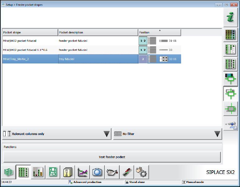
If waffle pack trays with fiducials are defined in the setup, the fiducials are displayed in the Setup –
Feeder pocket shapes view.
Figure 8-8: Fiducials for waffle pack trays
By selecting a fiducial and clicking on the Test feeder pocket button the fiducial is selected for
teaching.
Station Software 7xx to 714.0 (R20-2) / Feature Description 11/2020 Edition
134
8.11 Changing Acceleration Value for Waffle Pack Tray
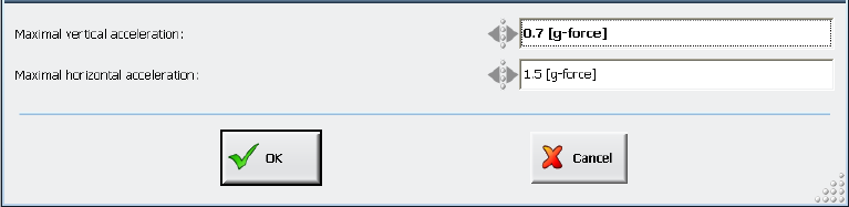
In the Setup view for waffle pack tray feeders, the acceleration values in Y- and Z-direction for
MTC and WPC may be changed at the station as of the Advanced production activity level. The
values are entered analogous to SIPLACE Pro (g= 9.81 m/s
2
) and the value ranges are also taken
over from SIPLACE Pro. However, no changes can be made for the Multiple JEDEC Tray Feeder
at the station.
Figure 8-9: Changing acceleration value
Provided that the "Download and Upload ..." handling option is set in SIPLACE Pro and the
operator at the station has the appropriate authorization, the changed acceleration values will be
uploaded to SIPLACE Pro and written into the SIPLACE Pro database.
If SIPLACE Pro rejects the access, the changed acceleration values will only remain locally at the
station until the next setup change or reboot.
8.12 Error Handling after Vision and Pickup Errors
Two new detailed warning and error messages have been introduced in response to frequent
Vision and pickup errors. The correspondent warning and error threshold can be set under
Settings – Machine options – Fault thresholds. The values are visible on all activity levels but
may only be changed as of the Machine service activity level.
Preset threshold values:
– Number of considered trials: 500 (cannot be changed by the operator)
– Warning threshold: 10 of 500 (= 2%)
– Error threshold: 25 of 500 (= 5%)
If the warning threshold is reached, a detailed warning will be displayed on the GUI and the pickup
position automatically corrected.
If the error threshold is reached, the track will be deactivated and the correspondent, detailed error
message displayed on the GUI.
Station Software 7xx to 714.0 (R20-2) / Feature Description 11/2020 Edition
135
8.13 Changing the Feeder Parameters – Enhancements
The feeder parameter change management has been adjusted and improved. The new features
are described in the following sections.
8.13.1 Orientation Check for Components
If the pickup angle was changed for components in a new tape feeder or waffle pack tray and this
is not immediately detected, the components might be placed incorrectly. To avoid such incorrect
placements, it is now possible to check if the orientation of a component is correct or not.
For this purpose, the affected components must be tagged in SIPLACE Pro and the orientation
check enabled. After one of the following cases has occurred, such components cannot be picked
up until the correct pickup angle has been confirmed with the Confirm Pin 1 position button:
– After a new setup has been downloaded
– After recognition of a splice point in the feeder
– After a feeder has been put on a component table
– Continuation after a foil torn
– Exchange of a magazine
An image of the component in the tape pocket and the target position is displayed at the station.
The operator may correct the angular position in error case.
8.13.2 Measuring the Pickup Position before Pickup
For large components, such as connectors, the tolerance for the position within the tape/waffle
pack tray pocket is often high. However, in many cases the pickup range is very small, and this
might lead to high reject rates.
For improved pickup reliability, the component top side can be measured automatically with the
PCB camera before the pickup to determine the exact position of the component within the tape
pocket.
The feature must be enabled for each single component in the Component Editor in SIPLACE Pro.
Then the component position is detected automatically and, if necessary, the pickup position will be
corrected automatically.
8.13.3 Enhanced Measuring Rule for Tape Pockets
Until now, a tape pocket measurement was performed when a tape pocket object was assigned to
a track in SIPLACE Pro or the maximum edge length of the component was <= 1 mm.
This rule has been enhanced so that a tape pocket measurement also will be performed if the
component type is MELF, SOT, SOxx or QFP and the maximum edge length <= 4 mm.