SIPLACE Station Software 7xx to 714 介绍.pdf - 第145页
Station Software 7xx to 714.0 (R20-2) / Feature Description 11/2020 Edition 145 8.26 SIPLACE Vision Enhancements The SIPLACE Vision syst em has been enhanced as follow s. 8.26.1 New Camera Interface GigE SIPLACE Vision n…
Station Software 7xx to 714.0 (R20-2) / Feature Description 11/2020 Edition
144
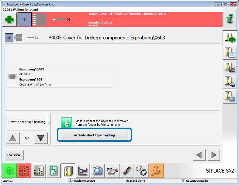
The Activate short tape handling option will then be displayed as solution in the Cover foil
broken … error message.
Figure 8-13: Activate short tape handling
By using the short tape handling mode, also the very last component can be picked up from the
tape. Thereafter, the production stops after the set number of pickup failures has been reached
(Stop placement after pickup failure setting is enabled in the Software options). The mode will
be terminated if one of the following events occurs:
– A new tape of normal length has been set up on the feeder. The tensioning of the cover foil
terminates the mode.
– The feeder has been removed and re-inserted.
– The placement machine or the station software has been restarted.
Station Software 7xx to 714.0 (R20-2) / Feature Description 11/2020 Edition
145
8.26 SIPLACE Vision Enhancements
The SIPLACE Vision system has been enhanced as follows.
8.26.1 New Camera Interface GigE
SIPLACE Vision now also supports GigE cameras.
8.26.2 Binning Can Be Disabled
With the so called "binning" 2x2 pixels (for sensor system type 30: 4x4 pixels) are combined to one
pixel. Thus, the resolution is lower, and the measure time reduced. Binning is performed
automatically for some components.
As of this station software version, binning can be disabled in the algorithm parameters on the
SIPLACE Vision GUI (value "1" = no binning). The setting is valid for the current sensor type only.
The parameter is available for all components and can be used on all placement machines.
8.26.3 Measuring Dies with Pattern Matching
Usually, the components are measured by SIPLACE Vision based on their electrical connectors
which are detected by filters specially adapted to the connector geometry. However, some dies
only show internal structures for which no suitable filters exist. With "pattern matching" it is now
possible to measure such structures more accurately.
At first, the pattern used for measuring the die will be created and taught by means of a teaching
wizard. Based on a reference die, points get measured at which the brightness strongly changes in
the picture. These points form the pattern.
All relevant calculations are performed automatically by the system. However, if necessary, the
operator may manipulate the teaching procedure by setting parameters. I.e., parts of the
component may be excluded from the teaching procedure (while not sure enough).
During the measurement of the component the position is detected at which the picture content
best matches the taught pattern points. At low concordance the component will be rejected.
8.26.4 New Pin Types: THT Round Pin and THT Square Pin
Two new pin types have been introduced to place THT components (Through Hole Technology):
THT round pin and THT square pin. The height of the components must be described as follows
in SIPLACE Pro:
– Height = pin length + base unit height
– A creep distance with height = pin length
Thus, an inspection with correct focusing can be performed in SIPLACE Vision.
8.26.5 Storing Vision Data
Until now, some Vision data as e.g. illumination values could be stored line- or station-specifically
without any security check.
As of this station software version, the same rules apply for such Vision data as for the other Vision
data (geometrical values). I.e., if the SIPLACE Pro security is enabled, the user must have the
corresponding authorization on the SIPLACE Pro computer.
Station Software 7xx to 714.0 (R20-2) / Feature Description 11/2020 Edition
146
8.27 Supported SIPLACE Pro Enhancements
The station software supports the placement of boards with a high number of panels.
Features (V707.1: Compatible Mode V706.2)
8.28 Twin Head / CPP Placement Heads on SIPLACE CA-Series
Compatible mode: Not supported
Additionally to the C&P20 M placement head, the CPP and Twin Head (also Twin Head HF)
placement heads are supported on the SIPLACE CA-series placement machines as of this station
software version with the following restrictions.
– Stationary cameras can only be installed on the locations 1 and 3.
– The Twin Head can only be installed on location 3.
– The CPP placement head is only supported in the high position on SIPLACE Wafer Systems.
CPP placement head
The CPP placement head can be used in Pick&Place mode and on SIPLACE Wafer Systems as
well. FlipChip and DieAttach modes are supported on the SIPLACE Wafer Systems. Dip modules
may be used.
The nozzle changer for the CPP placement head has 5 magazines for 20xx nozzles with 12
garages each and 1 magazine for 28xx nozzles with 9 garages. If desired, this configuration may
be changed, e.g. 6 magazines for 20xx nozzles.
Component camera type 33 is supported for placement in Pick&Place mode and component
camera type 30 on SIPLACE Wafer Systems.
Twin Head
The Twin Head is used in Pick&Place mode only.
The nozzle changer for the Twin Head has maximum 12 magazines with 2 garages each on the
locations 1 and 3 and maximum 10 magazines with 2 garages each on the locations 2 and 4.
Component camera types 33 and 25 are supported.
Available placement head configurations on SIPLACE CA-series
4*C&P20 M
2*C&P20 M in PA1 and 2*CPP in PA2
4*CPP
2*C&P20 M in PA1 and CPP / TH in PA2
2*CPP in PA1 and CPP / TH in PA2