SIPLACE Station Software 7xx to 714 介绍.pdf - 第147页
Station Software 7xx to 714.0 (R20-2) / Feature Description 11/2020 Edition 147 8.29 C&P20 P Placement Head on SIPLACE X-Se ries S Compatible mode: Not supporte d The C&P20 P placement head was introduced for the…
Station Software 7xx to 714.0 (R20-2) / Feature Description 11/2020 Edition
146
8.27 Supported SIPLACE Pro Enhancements
The station software supports the placement of boards with a high number of panels.
Features (V707.1: Compatible Mode V706.2)
8.28 Twin Head / CPP Placement Heads on SIPLACE CA-Series
Compatible mode: Not supported
Additionally to the C&P20 M placement head, the CPP and Twin Head (also Twin Head HF)
placement heads are supported on the SIPLACE CA-series placement machines as of this station
software version with the following restrictions.
– Stationary cameras can only be installed on the locations 1 and 3.
– The Twin Head can only be installed on location 3.
– The CPP placement head is only supported in the high position on SIPLACE Wafer Systems.
CPP placement head
The CPP placement head can be used in Pick&Place mode and on SIPLACE Wafer Systems as
well. FlipChip and DieAttach modes are supported on the SIPLACE Wafer Systems. Dip modules
may be used.
The nozzle changer for the CPP placement head has 5 magazines for 20xx nozzles with 12
garages each and 1 magazine for 28xx nozzles with 9 garages. If desired, this configuration may
be changed, e.g. 6 magazines for 20xx nozzles.
Component camera type 33 is supported for placement in Pick&Place mode and component
camera type 30 on SIPLACE Wafer Systems.
Twin Head
The Twin Head is used in Pick&Place mode only.
The nozzle changer for the Twin Head has maximum 12 magazines with 2 garages each on the
locations 1 and 3 and maximum 10 magazines with 2 garages each on the locations 2 and 4.
Component camera types 33 and 25 are supported.
Available placement head configurations on SIPLACE CA-series
4*C&P20 M
2*C&P20 M in PA1 and 2*CPP in PA2
4*CPP
2*C&P20 M in PA1 and CPP / TH in PA2
2*CPP in PA1 and CPP / TH in PA2
Station Software 7xx to 714.0 (R20-2) / Feature Description 11/2020 Edition
147
8.29 C&P20 P Placement Head on SIPLACE X-Series S
Compatible mode: Not supported
The C&P20 P placement head was introduced for the SIPLACE X4i S placement machine in the
previous station software version. As of the current station software version, this placement head is
additionally supported on the SIPLACE X2 S, X3 S and X4 S placement machines.
The C&P20 P placement head is supported on the same locations as the C&P20 A placement
head and uses the same component camera types (23 and 41), too.
The 4xxx nozzle type is supported on all locations.
Additionally, the diagnostic method for the pressure control valve of the C&P20 P placement head
has been improved. If applicable, detailed error messages and warnings will be displayed. The
machine will be stopped if the pressure supply fails or the pressure control valve gets superheated.
8.30 WPC5/WPC6 on SIPLACE X-Serie S
Compatible mode: Not supported
The station software supports the option to put a WPC5/WPC6 with the new WPC 40 X X-table on
the X2 S, X3 S and X4 S placement machines. However, the hardware will not be released for
series production in this version.
The WPC5/WPC6 and the WPC 40 X occupy the tracks 11 – 40. Further modules, such as
X-feeders may be set up on the tracks 1 – 10.
The WPC 40 X can be selected for location 2 in the Auto Configuration. A single WPC5/WPC6
cannot be configured without the X-table. An XFCU must have been installed.
Location 2 is displayed similarly as for the SX-series placement machines with WPC in the Main
view. WPC5/WPC6 and WPC 40 X can be selected via the corresponding buttons in the Setup
view.
The Twin Head and CPP placement heads and new nozzle changer / reject bin positions are
supported for this option.
SIPLACE Smart Pin Support supports the option on the X3 S and X4 S placement machines.
8.31 SIPLACE X4i S micron – Enhancements
Compatible mode: Not supported
CPP placement head and SIPLACE JTF-M feeder
As of this SIPLACE Pro version, the CPP placement head and the SIPLACE JTF-M feeder are
supported on the SIPLACE X4i S micron placement machine.
Placement Process for Component Type 03015
When placing components of type 03015, the user is guided through a similar placement process
as for component type 01005 on the SIPLACE X4i S micron placement machine.
If the placement process 01005 is selected in SIPLACE Pro, the required process parameters such
as cameras, nozzles, travel profiles and placement forces will be set automatically.
Station Software 7xx to 714.0 (R20-2) / Feature Description 11/2020 Edition
148
8.32 Placement Process for Springs
Compatible mode: Not supported
The station software provides a new travel profile to support the placement process for springs.
Special parameters must be set in SIPLACE Pro for this placement process.
8.33 Displaying Cutting Times per Compressed Air Cylinder on the
GUI
Compatible mode: Complete
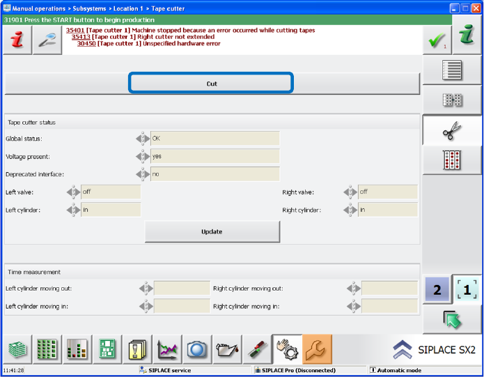
The cutting times per compressed air cylinder can be displayed on the station software GUI. Thus,
the sensor positions can be checked quickly, and the sensors adjusted if necessary.
The measurement of the cutting times is activated via the Cut button under Manual operations –
Subsystems.
Figure 8-14: Measurement of cutting times
The measured times for moving out and moving back the cylinder are displayed in a table in
milliseconds on the GUI for the left and right cylinders respectively.
The measurement only takes place within the Manual operations and not during production.