SIPLACE Station Software 7xx to 714 介绍.pdf - 第152页
Station Software 7xx to 714.0 (R20-2) / Feature Description 11/2020 Edition 152 Additionally, a precedence rule must be defined that the component at the bottom shall be placed first. Please also refer to sectio n 7.43. …
Station Software 7xx to 714.0 (R20-2) / Feature Description 11/2020 Edition
151
9 Feature Description – Station Software V708.x
Features (V708.0: Compatible Mode V707.2)
9.1 External Power Supply for X-Feeders
Compatible mode: Complete
This station software version supports the external power supply for X-feeders completely. The
external power supply has no functions in the station software but is displayed on the GUI and can
be locked and unlocked.
9.2 Software Support of the X-Module Upgrade Package
Compatible mode: Complete
The station software supports the X-Module Upgrade Package on the SIPLACE X-series S
placement machines. The package consists of the following modules:
– SIMATIC MicroBox 427D
– 4x CAN bus
– CIN CAN card
– IOCU 2
– MGCU
– SMPS (Switched Modular Power Supply)
– GigE cameras
The CAN interface supports up to four independent CAN buses. The CAN card (2x or 4x) must be
selected manually in the Auto configuration after the first start up.
The SMPS power supply offers advanced diagnostic checks (without GUI).
9.3 Placement of Stacked Components – Enhancement
Compatible mode: Complete
If components shall be placed on top of each other, the position of the first component must be
measured before the second component gets placed. For this, the fiducials of the first component
that has already been placed will be measured before the second component is picked up.
For this, an additional fiducial with the following content must be defined in SIPLACE Pro:
– Reference designator of the component at the bottom. Name: FOC_Reference Designator
(FOC = Fiducial on Component).
– Placement position reference to the component at the top.
Station Software 7xx to 714.0 (R20-2) / Feature Description 11/2020 Edition
152
Additionally, a precedence rule must be defined that the component at the bottom shall be placed
first.
Please also refer to section 7.43.
Detailed information can be found in the Version Description for SIPLACE Pro 12.0, item no.
[00197628-xx].
9.4 Analysis after Machine / Production Stop
Compatible mode: Complete
As of this station software version, the cause for the stop will be displayed additionally to the
35610 Machine stopped error message to better distinguish between machine and production
stops.
9.5 Improved Warnings for Critical Feeder Parameters
Compatible mode: Complete
There are new warning icons to avoid that differing, critical feeder parameters are overlooked and
ignored by the operator.
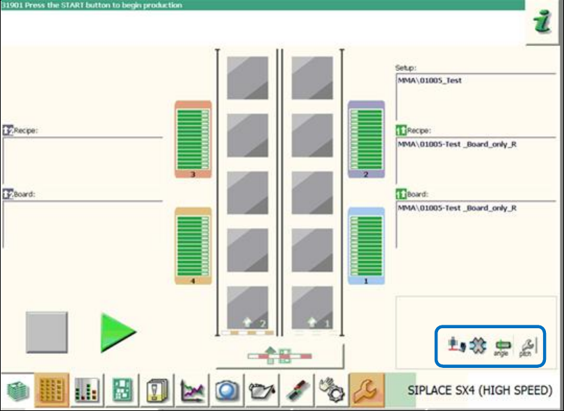
If a feeder pitch is too big or the pickup angle differs, the respective warning icons will be displayed
in the main view on the GUI as follows:
Figure 9-1: Warnings for critical feeder parameters
Station Software 7xx to 714.0 (R20-2) / Feature Description 11/2020 Edition
153
9.6 Measuring and Changing the Component Height
Compatible mode: Not supported
Inaccurate component height definitions may cause unnecessarily high reject rates. This shall be
prevented by measuring the height exactly with the component sensor and transmitting it to
SIPLACE Pro and/or adding it into the Component Shape Editor in SIPLACE Pro.
As of this station software version, the operator can test the component height at the station during
pickup. The placement head must be equipped with a component sensor and the nozzle /
component combination suitable for performing such a measurement.
If necessary, the operator can change the component height and upload it to SIPLACE Pro as of
the Advanced production activity level.
If SIPLACE Pro security is enabled, the operator logs on to SIPLACE Pro with a user account after
having downloaded a recipe. This user account must have write permission for the component
shape in the SIPLACE Pro database and also permission to upload objects to SIPLACE Pro.
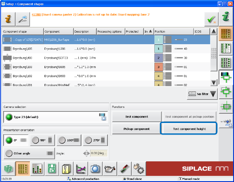
Figure 9-2: Testing the component height
If the new Test component height button is selected when the component shape is taught in the
station software, a new dialog box is opened in which the height measured by the component
sensor is displayed.