SIPLACE Station Software 7xx to 714 介绍.pdf - 第166页
Station Software 7xx to 714.0 (R20-2) / Feature Description 11/2020 Edition 166 9.22 Placement of Components 03015 / 0201 with C&P20 A or C&P20 P Compatible mode: Not supporte d The component shapes that can be s…

Station Software 7xx to 714.0 (R20-2) / Feature Description 11/2020 Edition
165
Prerequisites
– All stations in the line must be equipped with the same station software (version 708.1 or
higher).
– WDTL must be provided through the complete line. If a SIPLACE cluster is interrupted by a
device like an AOI system, WDTL is only possible via individual PCB barcodes.
9.20 "Feeding on Demand" Option for Tape Feeders
Compatible mode: Complete
As of this station software version, the Feeding on Demand option can be used for all tape
feeders. With this option it can be avoided that components remain in the tape without a cover foil
and fall out at a changeover.
The option is set in the SetupUnitTypes.xml configuration file and oriented either to the head cycle
or the board cycle dependent on the feeder type. For fast feeders like the 8 mm and 2x8 mm
X-feeders, the head cycle variant is used.
The board cycle variant can be enabled per station. Only one sequence for each feeder type can
be set and a mixture is not supported.
NOTICE
Components without a cover foil can possibly remain in the tape if a board is canceled,
i.e. if it has not been completely placed.
9.21 Configurable "Pickup Components during Measuring Fiducials"
Compatible mode: Not supported
Previously it was standard that the components were already picked up and measured while the
board entered the machine for a faster passing through. This practice was only suppressed if ink
spots had to be evaluated.
Now it can be configured in SIPLACE Pro if pre-pickup shall be performed always, never or
dependent of the recipe.
The option can only be overridden by correcting the configuration files of the station software
respectively. However, this should only be performed for test and integration purposes.

Station Software 7xx to 714.0 (R20-2) / Feature Description 11/2020 Edition
166
9.22 Placement of Components 03015 / 0201 with C&P20 A or C&P20 P
Compatible mode: Not supported
The component shapes that can be selected in SIPLACE Pro for the placement process are based
on the imperial units, i.e. on inches (1 inch = 2.4 cm) with one exception: component shape 03015
is based on the metric system.
As of this station software version, a new metric-based component shape 0201 can be defined in
addition to the existing, inch-based component shape 0201.
For the metric-based component shape0201, a new nozzle type has been introduced that is
supported by the C&P20 A and C&P20 P placement heads. The nozzle number 1002 is assigned
to the C&P20 A placement head and 4102 to the C&P20 P placement head.
NOTICE
Selection of the component shapes in SIPLACE Pro
In SIPLACE Pro, the component shapes 0201 (= inch-based) or 03015m
(= metric-based) can be selected for the placement process.
SIPLACE Pro treats the metric-based component shapes 0201 as component shapes
03015m. Therefore, in this case 03015m has to be selected and not 0201!
9.23 Optional Automatic Detection of the Feeder Pitch
Compatible mode: Complete
Components in tapes are often delivered with different feeder pitches dependent on the
manufacturer. In this case, the operator must adapt the pitch manually what might cause a big loss
of components from a tape reel if the setting is incorrect.
For this, the already available Automatic feeder pitch detection function (see section 5.7) has
been enhanced. As of station software version 708.1, an optional automatic feeder pitch detection
can be set and performed during runtime.
The automatic feeder pitch detection can currently solely be performed for 8 mm and 2x8 mm
X-feeders.
Prerequisite
The operator must be authorized to download from and upload to SIPLACE Pro, see
section 7.38.
Station Software 7xx to 714.0 (R20-2) / Feature Description 11/2020 Edition
167
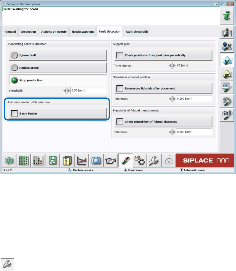
The function can be enabled or disabled in the Machine options on the GUI of the station
software.
Figure 9-12: Enabling Automatic feeder pitch detection
Functionality
The component nominal width is used to calculate the theoretically minimum possible value. The
feeder pitch detection starts with this minimum pitch. 10 components are picked up to check the
pitch setting. If pickup errors occur (pattern: OK, NOK, OK…), it is assumed that the setting is too
small, and the pitch will be increased by one step in the next step and the measurement repeated.
This process is repeated until pickup can be performed without pitch errors.
If the function is enabled, the feeder pitch detection is displayed by the following icon for deviating
parameter settings in the setup view of the locations: