SIPLACE Station Software 7xx to 714 介绍.pdf - 第174页
Station Software 7xx to 714.0 (R20-2) / Feature Description 11/2020 Edition 174 9.28 Enhancements in SIPLACE Vision The SIPLACE Vision syst em has been enhanced as follows: – Displaying a virtual keyboard Compatible mode…
Station Software 7xx to 714.0 (R20-2) / Feature Description 11/2020 Edition
173
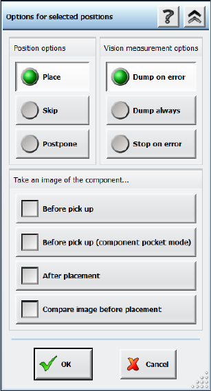
Figure 9-20: Placement error analysis options
After this option has been selected for one or several placement positions, the placement process
is interrupted before the z-axis starts to place the component and a new measurement with
reduced acceleration is started. The reduced acceleration shall prevent further slippage of the
components. After the additional measurement, the component is brought to the placement
position with reduced acceleration and will be placed with the z-axis acceleration that is defined in
SIPLACE Pro.
The two measurements (standard and before placement) can be compared and evaluated via the
inspection function for Vision measurements on the GUI. A possible slippage of the component can
thus be clearly recognized. Additionally, the results of the additional measurement are entered in
the board history files. This allows a statistical analysis over a longer period.
9.27 Robust Dual Gantry Measurement
Compatible mode: Complete
The dual gantry measurement procedure has been improved.
In a dual gantry configuration, the station software performs a dual gantry measurement every 5
minutes to correlate the gantries' positions and correct the positions, if necessary. Until now, if a
fiducial was manually taught or the wrong fiducial was detected by one of the gantries, the resulting
error was applied to all boards produced within the next 5 minutes.
To prevent such process errors, the dual gantry correction will now not be transferred to the next
board(s) if any of the fiducial positions were taught by the operator. This includes all cases in which
the first fiducial measurement failed, and the operator intervened via a detailed error. Instead, a
new dual gantry measurement will be performed for the next board.
Station Software 7xx to 714.0 (R20-2) / Feature Description 11/2020 Edition
174
9.28 Enhancements in SIPLACE Vision
The SIPLACE Vision system has been enhanced as follows:
– Displaying a virtual keyboard
Compatible mode: Compatible
SIPLACE Vision automatically displays a virtual keyboard on the GUI of the station software
whenever a text entry field has been selected. This behavior must be configured in the station
software beforehand.
The virtual keyboard is not displayed on the GUI of the Vision Teach Station because a
keyboard is always available in this case.
– Modifications to allow reading of individual barcode fiducials by the board camera.
Compatible mode: Complete
– Improved procedure to teach the pickup position if the camera is outside the travel range due to
a slight rotation.
Compatible mode: Compatible
– If connection problems occur in the communication with the GigE cameras, the errors are
narrowed down by specific queries and detailed error messages displayed.
Compatible mode: Complete
– Correction in the calculation of the scaling of MFU components.
Compatible mode: Complete
Features (V708.1 SP1: Compatible Mode V707.3 SP1)
This version does not contain any new features.
Features (V708.1 SP2: Compatible Mode V707.3 SP2)
This version does not contain any new features.
Station Software 7xx to 714.0 (R20-2) / Feature Description 11/2020 Edition
175
10 Feature Description – Station Software V709.x
Features (V709.0)
10.1 SIPLACE TX-Series – SIPLACE TX1/TX2/TX2i Placement
Machines
The station software supports the SIPLACE TX1/TX2/TX2i placement machines of the new
SIPLACE TX-series. The main features of the SIPLACE TX-series are presented in the following
sections.
10.1.1 Machine Configurations and Placement Head Combinations
The SIPLACE TX-series placement machines are provided in the machine configurations and
placement head combinations listed below.
The SIPLACE TX1/TX2 and SIPLACE TX2i machine configurations are equipped with different
covers. The indicator lamp system is the same as for SIPLACE X-series S.
Machine configurations
Placement head combinations
TX1
One gantry, two tables
*)
, table on
location 1 in outer position
C&P20 P or
CPP or
Twin Head
TX2
Two gantries, two tables
*)
, table on
location 1 in outer position
C&P20 P + C&P20 P or
CPP + CPP or
CPP + Twin Head
TX2i
Two gantries, two tables
*)
, table on
location 1 in inner position
C&P20 P + C&P20 P or
CPP + CPP
*)
Table on location 2 always in inner position
Table 10-1: Machine configurations and placement head combinations SIPLACE TX-series
NOTICE
Restricted travel range
– for Twin Head:
The right segment cannot reach 3 tracks on the left side of the table,
the left segment cannot reach 3 tracks on the right side of the table.
– for C&P20 P placement head:
Tracks 1-2 cannot be reached on location 1.