SIPLACE Station Software 7xx to 714 介绍.pdf - 第181页
Station Software 7xx to 714.0 (R20-2) / Feature Description 11/2020 Edition 181 10.1.7 Fast Head Exchange The Fast Head Exchange option is supported for the C&P20 P and CPP placement heads o n the TX -series machines…
Station Software 7xx to 714.0 (R20-2) / Feature Description 11/2020 Edition
180
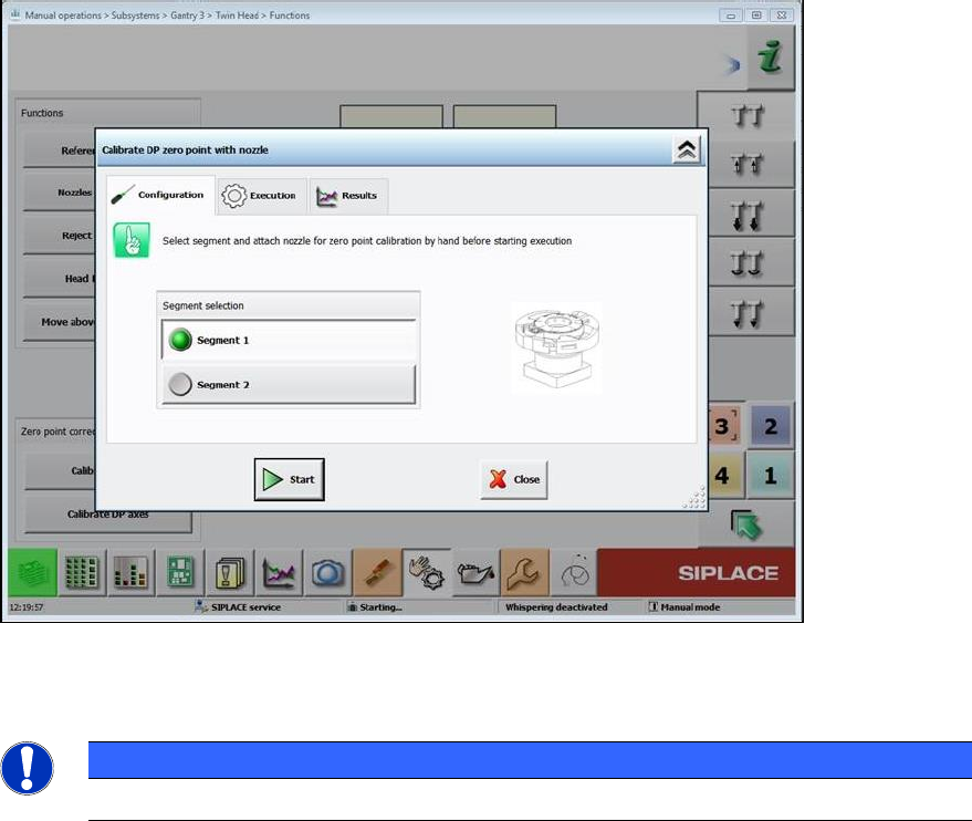
10.1.5 Calibration of Twin Head with Stationary Flip Chip Camera and Calibration
Nozzle
For lack of space, stationary IC and Flip Chip cameras cannot be mounted simultaneously in the
SIPLACE TX-series placement machines. Therefore, the Flip Chip camera is used together with a
special calibration nozzle (no. 502) to calibrate the Twin Head.
The software checks if the calibration must be performed with the calibration nozzle, i.e. if no IC
camera is mounted. The operator is prompted on the GUI to attach the calibration nozzle on a
segment of the Twin Head and confirm it in the Manual operations.
Figure 10-6: Attaching calibration nozzle
The procedure must be performed separately for each segment.
HINWEIS
The calibration nozzle must not be used as a standard nozzle!
10.1.6 Calibration Steps to Support Machine Dynamics
To achieve higher accuracy of the gantry axes, the following two calibration steps must be set
under Machine Service – Automatic calibration:
– X-axis parametrization
– System identification
The results are automatically stored without confirmation.
Station Software 7xx to 714.0 (R20-2) / Feature Description 11/2020 Edition
181
10.1.7 Fast Head Exchange
The Fast Head Exchange option is supported for the C&P20 P and CPP placement heads on the
TX-series machines in the same way as for the X-series machines and with the same restrictions.
Additionally, the "X-axis parametrization" step is performed during calibration. Please also refer to
section 10.9.1.
10.1.8 Fault-Tolerant Operation
To prevent a complete line down time, the placement head of each gantry can be set to "No head
installed".
This state can be enabled and disabled in the Auto Configuration under Service – Machine
configuration.
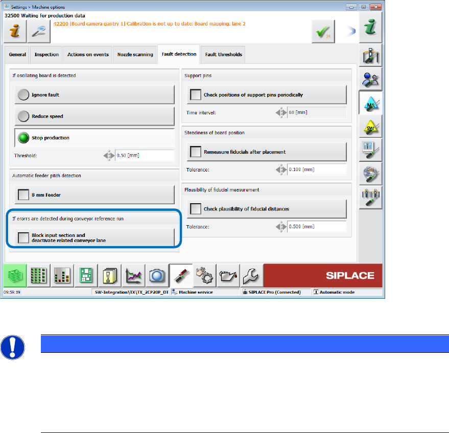
If errors occur during the conveyor reference run, the related conveyor lane can also be disabled
under Settings – Machine options – Fault detection.
Figure 10-7: Disabling conveyor lane
NOTICE
The Auto configuration cannot distinguish between a TX1 machine with no placement
head on gantry 2 and a TX2 machine with disabled placement head on gantry 2.
Therefore, if the placement head is disabled on gantry 2 of the TX2 machine, the nozzle
changer configuration for the TX1 machine will be configured and all nozzle and
calibration data on location 2 deleted. After reactivating the placement head on gantry 2
of the TX2 machine, the nozzle changer on location 2 must be calibrated
10.1.9 Checking the Fans
– The state of all fans is retrieved and displayed under Subsystems on the station software GUI.
– A fan check can be performed during maintenance, see section 10.9.
Station Software 7xx to 714.0 (R20-2) / Feature Description 11/2020 Edition
182
10.1.10 Locking / Unlocking the Cover
The station software supports the hardware that locks and unlocks the cover of the SIPLACE
TX-series placement machines.
The cover is automatically locked during production or manual interventions and automatically
unlocked if production is stopped due to an error.
After a Manual Operation has been finished, the cover will not be unlocked automatically because
it is assumed that other Manual Operations will follow immediately. Thus, a too frequent unlocking
and locking is prevented.
Example:
Stepping the star axis once is such a Manual Operation; stepping the star axis multiple =
multiple Manual Operations.
The cover can be unlocked manually by pressing the Stop or Emergency stop button at the
machine. In this case, the currently running process (production or Manual Operation) is stopped
before the cover is unlocked.
Additionally, an interior lighting in the cover improves the visibility and switches on automatically as
soon as the cover is unlocked. If the cover is locked, the lighting switches off automatically.
10.1.11 Creating Bug Report with Virtual Keyboard
A keyboard is required to create a bug report, e.g. to enter text manually. As of this station software
version, a virtual keyboard is provided for this purpose.
If the operator touches the touch screen in one edge with one finger, performs a diagonal gesture
to the opposite edge and then stops pressing the touch screen, the Bug Reporter starts. The
gesture is recognized in both directions and for both diagonals. Whenever a keyboard is required,
the virtual keyboard will be displayed automatically.
Restrictions
Cannot be used in the following cases:
– Changing the assignment of activity level to a button (right mouse key)
– During operating system installation as well as during any other software installation requiring
operating system administrator login.
10.1.12 Other Features
– The supported cameras, nozzle types and component spectra of SIPLACE TX-series can be
found in the SIPLACE TX User Manual, item no. [00197975-xx].
– Barcode reader and the Reading Barcode recognition with PCB Camera and Whispering of
Barcodes options are supported.