SIPLACE Station Software 7xx to 714 介绍.pdf - 第19页
Station Software 7xx to 714.0 (R20-2) / Feature Description 11/2020 Edition 19 The following changes have been made in the station software: – Four conveyor lanes are displayed in the "Produ ction" view on the …
Station Software 7xx to 714.0 (R20-2) / Feature Description 11/2020 Edition
18
3.5 Tray Feeding
The station software supports the following types of tray feeding on the X2, X3 und X4 placement
machines:
Manual tray feeding:
– Arbitrary Carrier X
– Carrier X
Automatic tray feeding:
– MTC2 on locations 2 and 4.
3.6 New Conveyor Mode "Quad Lane"
Provided that the machine has been configured accordingly, the station software supports the new
"Quad Lane" (QC) conveyor mode additionally to single (SC) and dual (DC) conveyor modes.
The basic principle of "Quad Lane" is that four boards are placed simultaneously on four conveyor
lanes. This increases the overall line performance, especially for boards with a low number of
placement positions. In SIPLACE Pro two boards respectively are defined as a logical pair (2L/2R
and 1L/1R, from left machine side to right machine side). This pair is downloaded in one single job
from SIPLACE Pro to the station. The logically coupled lanes xL and xR are referred to as sub-
lanes. The board width may be different in the 2L/2R and 1L/1R lanes, but all boards must have the
same thickness. The conveyor width is automatically adjusted in the job specification (if automatic
width adjustment is preset in SIPLACE Pro).
Also, single boards may be placed in the sub-lanes. In this case a board must be defined in the job
specification for the sub-lane next to the fixed conveyor edge. Otherwise, the width of this sub-lane
is unknown.
Boards can be aborted separately. However, two boards on one conveyor lane are always
conveyed together. An aborted board is conveyed to the output conveyor together with the placed
board. The placed board will not be driven into the next machine until the aborted board has been
removed from the output conveyor.
The "Quad Lane" conveyor mode is supported on the X4 and X4i placement machines.
Station Software 7xx to 714.0 (R20-2) / Feature Description 11/2020 Edition
19
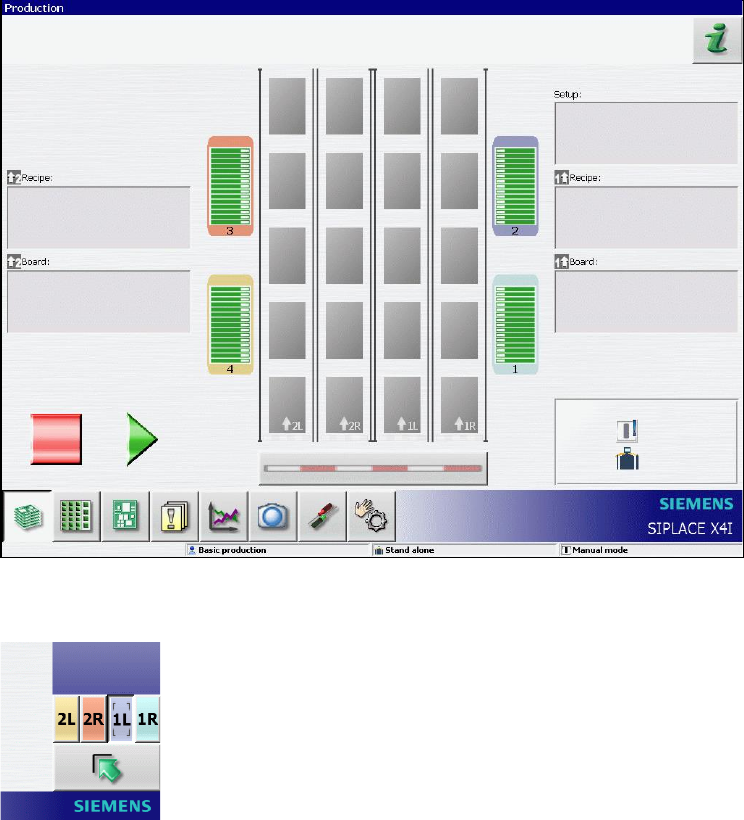
The following changes have been made in the station software:
– Four conveyor lanes are displayed in the "Production" view on the GUI main view, when "Quad
Lane" conveyor mode is activated.
– New buttons are used on the GUI to operate the single sub-lanes:
3.7 Single Conveyor Mode on X4i
The single conveyor mode is also supported on the X4i placement machine as of this station
software version.

Station Software 7xx to 714.0 (R20-2) / Feature Description 11/2020 Edition
20
3.8 New Dip Module LDU_X for X-Tables
The new type of dip module, the linear dipping unit (LDU_X) is supported on X-type feeder tables.
The dip process is supported by all placement heads (C&P20A, CPP, Twin) on the X-series
placement machines. By the station software the LDU_X module is handled like any other X-
feeder. On the GUI of the station software the LDU_X module is displayed in the Feeder,
components and nozzles view.
CAUTION
In setup operation (activated through the unlocked key-operated switch), the operator is
able to start a squeegee cycle. However, if the LDU_X is used in the current product,
and the machine was not stopped and the LDU_X is operated parallel in setup mode,
this might damage the placement head!
3.9 Accuracy Check Tool (ACT)
With the Accuracy Check Tool (ACT) the placed components on a PCB can be measured for all
placement heads of the X series. For this a special glass PCB with many high-precision measured
fiducials and ACT component equipment are used. Depending on the selected placement head,
glass or ceramic components will be placed on the measuring board. Subsequently, the placed
components are measured with the PCB camera. The results can be saved in a pdf file.
ACT is called in the Service – Accuracy Check view.
This function requires the "SIPLACE Service" activity level.
A detailed description can be found in the ACT user guide, item no. 00196351-xx, and in the online
help to the station software.
3.10 Fast Head Exchange
To increase the availability of the placement machines, repairs should be carried out as fast as
possible or be completely avoided by performing regular maintenance outside of the machine. The
station software automatically detects if a head exchange has been performed, and if maintenance
is planned for placement heads, the placement machines and the nozzle configuration can be
optimally prepared for an exchange. During fast head exchange the calibration is replaced by a
"short calibration" and the operator is guided through a wizard for updating the nozzle
configuration. The wizard can be found in the Service view and should be called before the actual
exchange takes place. This function requires the "Machine Service" activity level.
CAUTION
Placement head and camera always have to be exchanged together, otherwise a
complete calibration is required!