SIPLACE Station Software 7xx to 714 介绍.pdf - 第193页
Station Software 7xx to 714.0 (R20-2) / Feature Description 11/2020 Edition 193 10.12 Independent Place ment – 2- in -1 Mode Compatible mode: Complete I-Placement is a placement mode in a dual gantry placement area, wher…
Station Software 7xx to 714.0 (R20-2) / Feature Description 11/2020 Edition
192
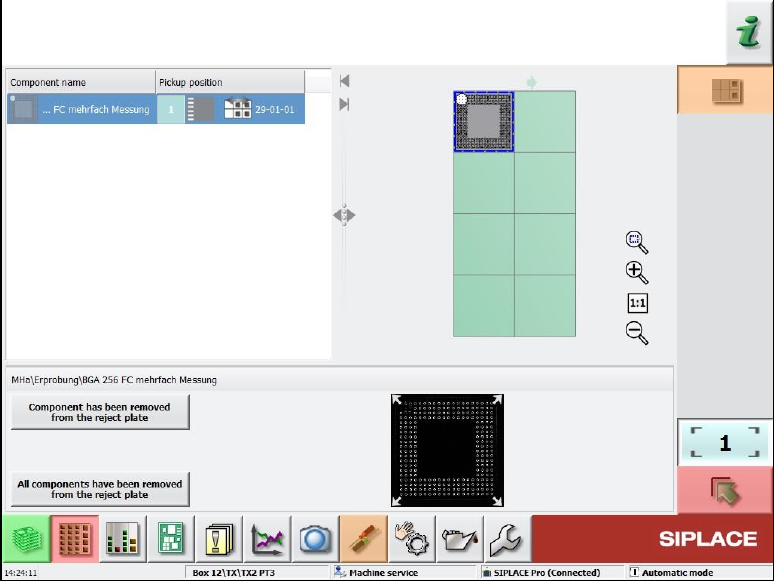
By selecting the reject plate button, the following dialog box opens:
Figure 10-16: Rejected components on the reject plate
This dialog box contains a list of the components put onto the reject plate and a graphical
representation (grid) of the plate with the components on it. A component can be selected from the
list or in the grid, the selection is automatically synchronized.
Additionally, the pickup position from where the component was picked up is displayed. If a
component was picked up from a tray, only the level and magazine number are displayed, not the
pickup position in the magazine!
Once a component has been selected, the attached Vision dump is displayed (if still existing on the
drive).
With this information the operator can check whether the component is ok or not and decide to put
it back in the feeder again. This requires that the feeder from which the component was picked up
is still inserted in the machine at the same location.
The operator can confirm the removal of the component from the reject plate with the Component
has been removed from reject plate button. Confirmation must be done for each component.
A multiple selection is not available.
10.11.2 Increased Component Range for Twin Head
Until now, the component range for Twin Head on SIPLACE TX-series placement machines was
limited to 55 x 45 mm due to the reject bin size. To allow larger connectors to be placed, the
component range has been increased to 75 x 10 mm from this station software version. For this,
the nozzle reject bin must be removed from the side on which the Twin Head is mounted. If the
components are correspondingly marked in SIPLACE Pro, they will be rejected onto the reject
plate.
Station Software 7xx to 714.0 (R20-2) / Feature Description 11/2020 Edition
193
10.12 Independent Placement – 2-in-1 Mode
Compatible mode: Complete
I-Placement is a placement mode in a dual gantry placement area, where every gantry only places
components on the board of the assigned conveyor lane. This mode can be used to boost
performance and decouple the operation of the left and right conveyor lane. From this station
software version, it is also possible to operate the placement machine independently for the two
lanes. The placement machine is then running in 2-in-1 mode.
Prerequisites
– 2-in-1 mode only applies for dual conveyor placement machines in which independent jobs
have been started on both lanes.
– The two recipes must have no gantry in common (for placing, measuring) on this placement
machine.
The following actions can be performed on one conveyor lane while another product is being
produced on the other conveyor lane:
– Teaching board fiducials
– Teaching fiducials for feeder modules (e.g. component pocket)
– Teaching component shapes
– Pin1 detection
– Correcting pickup position
– Teaching placement positions
– Inspecting a position to decide whether it should be placed or not
– Teaching trays
– Skipping a placement head segment
– Changing the placement list
Station Software 7xx to 714.0 (R20-2) / Feature Description 11/2020 Edition
194
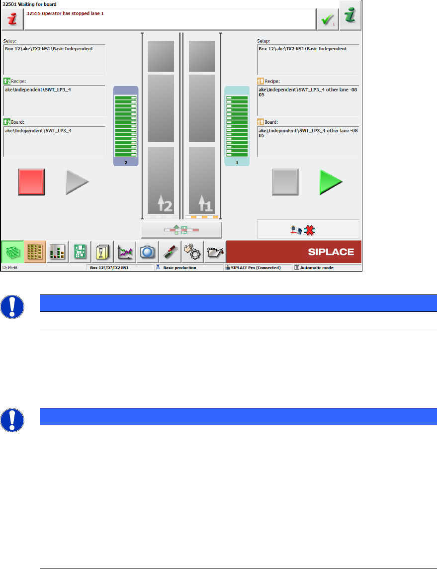
If the placement machine runs in 2-in-1 mode, the Start and Stop buttons are duplicated on the
station software GUI:
Figure 10-17: Start and Stop buttons for each conveyor lane
NOTICE
The 2-in-1 mode has no effect on the hardware Start and Stop buttons!
In the example above, conveyor lane 1 has been stopped (conveyor is blocked, Start button is
highlighted) whereas conveyor lane 2 is producing (conveyor is open, Stop button is highlighted).
If a different job is started via SIPLACE Pro (or in standalone mode) that does not qualify for
2-in-1-mode, the GUI would revert to a single Start/Stop button.
NOTICE
The notion of Start/Stop extends to the job on the left or right conveyor and to all
gantries associated with that job! Assuming an SX2 placement machine in I-mode this
intuitively results in gantry 1 starting/stopping in conjunction with the job on conveyor
lane 1 (likewise for conveyor lane 2 and gantry 2).
However, if "Borrow Performance" is used (please refer to chapter Fehler!
Verweisquelle konnte nicht gefunden werden.), there might be a job on conveyor lane
1 that is processed by both gantry 1 and 2 while conveyor lane 2 is just driving the
boards for a different job through the machine. Now stopping the job on conveyor lane 1
(the right Stop button) would block conveyor 1 and stop gantry 1 and gantry 2!
Conversely, pressing the left Stop button would only block conveyor lane 2, but not affect
gantry 2.