SIPLACE Station Software 7xx to 714 介绍.pdf - 第217页
Station Software 7xx to 714.0 (R20-2) / Feature Description 11/2020 Edition 217 Stereo Measurements for pi ns This option can be enabled if a multiple measurement is requi red for an OSC component. For each measurement, …
Station Software 7xx to 714.0 (R20-2) / Feature Description 11/2020 Edition
216
11.5 Odd Shape Components – OSC Package Option
Compatible mode: Not supported
The station software supports a bundle of new features for odd shape components (OSC) as of
station software 710.0. These features have been collected into the OSC Package option. This
option must be enabled in SIPLACE Pro for the station(s) concerned. The option requires the
Vision OSC Package - Machine Connection floating license. The license must be available at
download if any of the supported features shall be used.
Following features are supported by the OSC Package option:
● Vision OSC measuring options:
– User-defined "Odd shape component"
– Stereo measurement for pins
– Special position evaluation – "Alignment" attribute
● Increased placement force of Twin VHF placement head to 100 N
● Improved placement of snap-in components
– Specification of Z-threshold
● Support to find best acceleration
The single features are presented below.
11.5.1 Vision OSC Measuring Options
The following measuring options are available in SIPLACE Vision if the corresponding license is
installed and the OSC Package option enabled.
User-defined Odd shape component
The new Pattern Feature lead type allows the user to describe arbitrary abstract patterns on a
component. These patterns can only be created and taught in the Component Shape wizard of
SIPLACE Vision.
Example
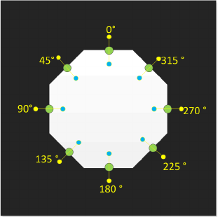
Figure 11-2: Pattern Feature
Station Software 7xx to 714.0 (R20-2) / Feature Description 11/2020 Edition
217
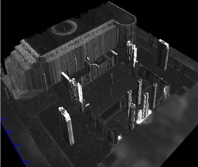
Stereo Measurements for pins
This option can be enabled if a multiple measurement is required for an OSC component. For each
measurement, two images are taken offset to each other in X-direction. Through stereo matching, a
height image will then be computed from these two images (i.e. the distance to the camera can be
computed for each pixel in the images).
Example
Figure 11-3: 3D display of the stereo measurement height image
If stereo measurement is enabled or the Edit parameter button has been pressed, a dialog box
opens in which illumination and traversing path can be set.
The option can only be enabled for stationary cameras of the types 25 and 33 (and thus for Twin
and CPP placement heads only) with the following restrictions:
Camera type 25: minimum feature size = 75 µ
Camera type 33: minimum feature size = 200 µ
The measurement of THT components (Through Hole Technology) with 2 or 3 pins is handled as a
special case. If a component contains 2 or 3 connectors of the types THT round pin or THT
square pin and no other feature groups are available, an automatic measuring process will be
performed during the stereo measurement.
Special Position Evaluation
For OSC components it is often difficult to find the X-/Y-position and determine the rotation of a
component by using the same feature. Therefore, a new function has been introduced that allows
using one feature for the X-/Y-alignment and another one for the rotational alignment.
The new Alignment attribute is displayed as parameter of the respective feature group on the GUI.
The attribute is only visible in SIPLACE Vision.
Station Software 7xx to 714.0 (R20-2) / Feature Description 11/2020 Edition
218
Following settings are available for the special position evaluation:
Setting
Evaluation
Default
Default value, normal evaluation (X, Y, angle)
Do not use
Group is not used to determine the component position (but for inspection)
Angle
Group is only used to determine the angle
X and Y
Group is only used for X and Y, not for the angle
X
Group is only used for X, not for Y and angle
Y
Group is only used for Y, not for X and angle
X and angle
Group is only used for X and angle, not for Y
Y and angle
Group is only used for Y and angle, not for X
The X- and Y-coordinates always refer to the component coordinate system.
Example
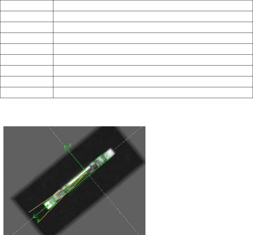
Figure 11-4: Alignment of a twisted pin
The pin shall be placed so that the connector to the left is precisely positioned on the pad even if
the pin length differs from the target. The angle results from the angle between the two ends.
Model:
Alignment for the connector to the left is Default because it shall be used for X, Y and angle.
Alignment for the connector to the right is Angle because it shall only be used to determine the
angle.
Thus, the angle from the two connectors will be determined at first. Then the position will be
determined so that the component is only aligned by the connector to the left.
11.5.2 Increased Placement Force of Twin VHF
The placement force has been increased from 70 N to 100 N for the Twin VHF placement head
with item no. [03096701-03]. The cool down time calculation has been adapted for the new range
from 70 N up to 100 N.
Placements with a force greater than 70 N are not supported on stations with software versions
< 710 and Twin VHF placement heads with a functional status < [-03]. Such placements will be
forced onto stations with station software version >= 710 by SIPLACE Pro.