SIPLACE Station Software 7xx to 714 介绍.pdf - 第220页
Station Software 7xx to 714.0 (R20-2) / Feature Description 11/2020 Edition 220 When the board enters the output secti on, a detailed message is displ ayed. Figure 11 -6: Confirming placement pos itions It contains: – Th…
Station Software 7xx to 714.0 (R20-2) / Feature Description 11/2020 Edition
219
11.5.3 Improved Placement of Snap-In Components
The feature for placement of snap-in OSC components has been improved. With this feature, the
system can check whether the pins of such components are "snapped-in", i.e. completely inserted.
The actual Z-axis position of every snap-in placement will be compared with its corresponding
height reference value. These values must match each other. It is recommended to set support
pins close to the snap-in placement positions.
The snap-in placement process must be enabled for the component shape in SIPLACE Pro.
Additionally, the snap-in threshold that will be used for comparing the two values has to be
specified in mm.
After the first board has been completely produced, it will be transferred to the output section or the
configured inspection location and marked for manual inspection. The operator must inspect every
snap-in placement position and confirm whether the placement is correct or not. If correct, the
corresponding Z-axis position will be stored as reference position and used as placement position
for all subsequent boards. If not correct or if subsequent boards are already produced before the
height reference values have been taught, the measured height will be ignored, and the operator
must confirm the height whenever the next component is placed.
The height reference values are not uploaded to SIPLACE Pro. Thus, when the job at the
placement machine is changed or the machine is shut down, the height reference values must be
taught again.
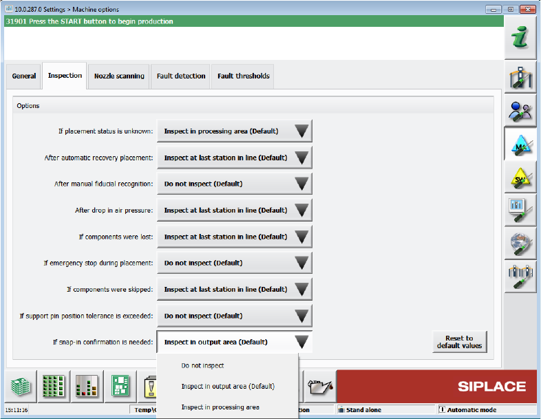
The position where the operator can inspect the board is configurable under Machine options –
Inspection – If snap-in confirmation is needed. Default option: Inspect in output section.
Figure 11-5: If snap-in confirmation is needed
Station Software 7xx to 714.0 (R20-2) / Feature Description 11/2020 Edition
220
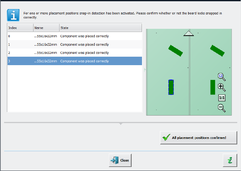
When the board enters the output section, a detailed message is displayed.
Figure 11-6: Confirming placement positions
It contains:
– The position of the board in the machine.
– A list including all placement positions on the board which must be confirmed.
– A graphical board overview in which the selected items in the list are highlighted.
There are two options for each row in the list:
– Component was placed correctly
The Z-height will be set as good for the snap-in detection.
– Repeat measurement
The measured height will be ignored, and the user must confirm the height whenever the next
component is placed. The board keeps marked for inspection.
After setting the results for all placement positions, the settings must be confirmed with the All
placement positions confirmed button.
In the Placement positions view, there are two new icons under the Options column:
– Snap-in confirmation required
is displayed if the correct Z-height has not yet been confirmed by the operator.
– Snap-in detection active
is displayed if the confirmation has already been done by the operator.
Station Software 7xx to 714.0 (R20-2) / Feature Description 11/2020 Edition
221
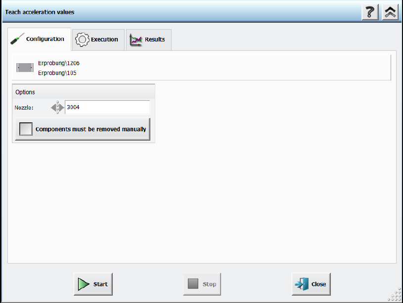
11.5.4 Support to Find Best Acceleration
A new teaching function supports finding the highest acceleration or speed values for a component
shape. For this, the dialog for teaching component shapes has been enhanced by the new Teach
acceleration values menu entry under Actions as of the Machine service activity level. By
triggering this action, a Configuration page is displayed.
Figure 11-7: Teach acceleration values – Configuration
Following decisions must be made:
– Nozzle to be used
If the user wants to perform the teaching with another nozzle, the nozzle can be selected from
a list. Only available nozzles will be displayed.
– Option for disabling the rejection of components
The default value is to reject the components automatically. But if the Components must be
removed manually option is set, the operator will be prompted to remove the component
manually from the placement head as soon as the check fails. The option is only available for
placement heads for which this is possible. Once set, the value is saved for the next run.