SIPLACE Station Software 7xx to 714 介绍.pdf - 第223页
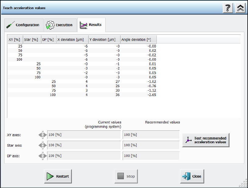
Station Software 7xx to 714.0 (R20-2) / Feature Description 11/2020 Edition 223 Figure 11 -9: Teach accel eration values – Results The recommended value s can be compared with the valu es of the programming system. Diffe…
Station Software 7xx to 714.0 (R20-2) / Feature Description 11/2020 Edition
222
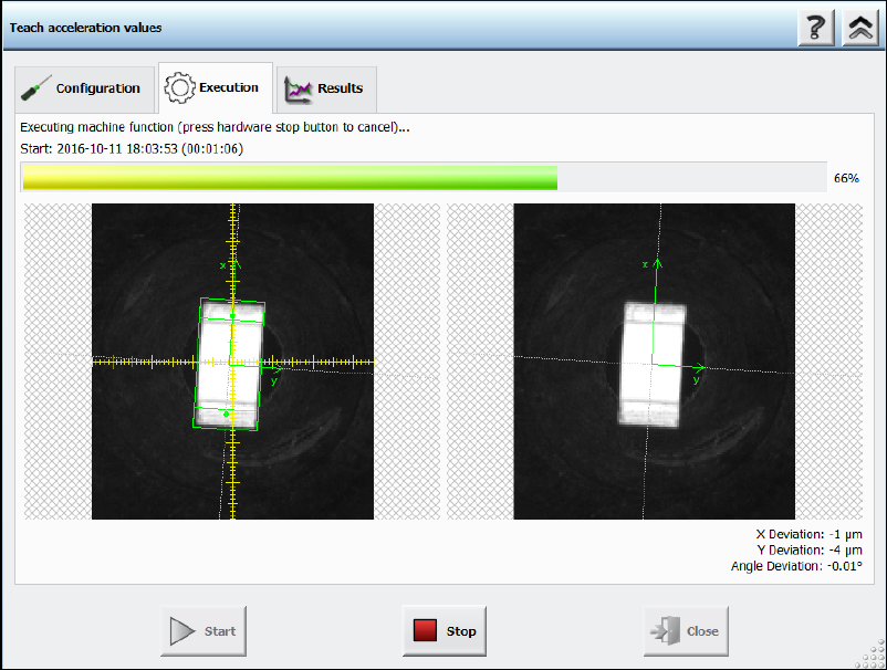
After pressing the Start button the Execution page will be opened.
Figure 11-8: Teach acceleration values – Execution
The execution steps are displayed together with the reference Vision image and the last Vision
image done by the camera. Additionally, the current acceleration values of the axes and the
measured deviations are displayed. If the operator must remove a component from the placement
head manually or if the component is lost, a hint will be displayed, and the operator must confirm
the action to continue.
If an error occurs during execution, the error causes are displayed on the last page in an error list.
Otherwise, the results are presented in a table with all the measured values of the deviations and
the recommended accelerations values.
Station Software 7xx to 714.0 (R20-2) / Feature Description 11/2020 Edition
223
Figure 11-9: Teach acceleration values – Results
The recommended values can be compared with the values of the programming system. Different
values are highlighted. Usually, the recommended values will be tested after measurement. For
this, the Test recommended acceleration values button is offered. If pressed, the teach dialog
will be closed and the test dialog opened.
If the acceleration value of an axis is not relevant for the measurement, an empty cell will be
displayed. The displayed axes depend on the used placement head. A line displaying the value of
the vacuum system will be displayed if a vacuum pump is used in the machine. Thus, the operator
can check that the acceleration values were determined while having a value like the one during
production.
The upload to SIPLACE Pro is not available until the recommended values have been tested.
Station Software 7xx to 714.0 (R20-2) / Feature Description 11/2020 Edition
224
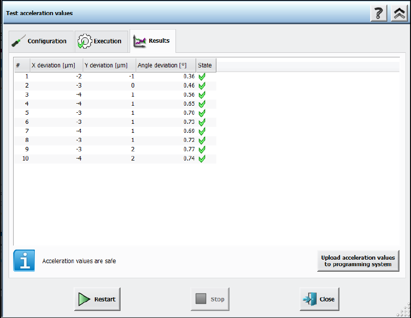
Figure 11-10: Test acceleration values – Results
11.6 New Fiducial Type – Notch
Compatible mode: Not supported
U-shaped board notches can now be measured with the new Notch fiducial type. This fiducial type
is only relevant for rectangles with rounding. Only the rounding in the upper and lower left corners
(in 0° orientation) are considered for measurement.
11.7 Special Fiducial Evaluation for LED Centering
Compatible mode: Complete
Current manufacturing processes of lighting products require placement of LED components
precisely aligned relative to oblong holes or other features of the board.
For this, the new Evaluation Mode fiducial type attribute has been introduced to provide additional
information for describing such features. In SIPLACE Pro, the Evaluation Mode can be selected,
indicating how fiducial positions using the current fiducial type shall be evaluated by the station
software. The user can select between the Standard (X,Y) and the Y evaluation modes.
In the Standard (X,Y) evaluation mode, the station software will consider the X and Y data of the
fiducial position (default, used by all "old" fiducials).
The Y evaluation mode is suitable for oblong holes or notches. The station software will only use
the measured Y data for panel correction. The X target position is only used to determine where to
position the camera and the angle describes the direction of the oblong hole / notch with respect to
the panel.
If the Y evaluation mode is selected for at least one fiducial in the recipe, a corresponding
SIPLACE LED Centering – Machine Connection license is required for each machine of the line.