SIPLACE Station Software 7xx to 714 介绍.pdf - 第225页
Station Software 7xx to 714.0 (R20-2) / Feature Description 11/2020 Edition 225 11.8 Simplified Tray Teaching for Standard Trays Compatible mode: Complete A simplified tray teaching h as been implemented for s tandard tr…
Station Software 7xx to 714.0 (R20-2) / Feature Description 11/2020 Edition
224
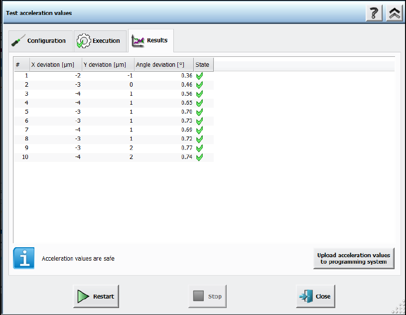
Figure 11-10: Test acceleration values – Results
11.6 New Fiducial Type – Notch
Compatible mode: Not supported
U-shaped board notches can now be measured with the new Notch fiducial type. This fiducial type
is only relevant for rectangles with rounding. Only the rounding in the upper and lower left corners
(in 0° orientation) are considered for measurement.
11.7 Special Fiducial Evaluation for LED Centering
Compatible mode: Complete
Current manufacturing processes of lighting products require placement of LED components
precisely aligned relative to oblong holes or other features of the board.
For this, the new Evaluation Mode fiducial type attribute has been introduced to provide additional
information for describing such features. In SIPLACE Pro, the Evaluation Mode can be selected,
indicating how fiducial positions using the current fiducial type shall be evaluated by the station
software. The user can select between the Standard (X,Y) and the Y evaluation modes.
In the Standard (X,Y) evaluation mode, the station software will consider the X and Y data of the
fiducial position (default, used by all "old" fiducials).
The Y evaluation mode is suitable for oblong holes or notches. The station software will only use
the measured Y data for panel correction. The X target position is only used to determine where to
position the camera and the angle describes the direction of the oblong hole / notch with respect to
the panel.
If the Y evaluation mode is selected for at least one fiducial in the recipe, a corresponding
SIPLACE LED Centering – Machine Connection license is required for each machine of the line.

Station Software 7xx to 714.0 (R20-2) / Feature Description 11/2020 Edition
225
11.8 Simplified Tray Teaching for Standard Trays
Compatible mode: Complete
A simplified tray teaching has been implemented for standard trays. In the Simplified Tray-Editor
dialog, a graphic displays the positions of all components within the tray. The operator can enter
the number of rows and columns of the tray as well as the height of the component seating and
teach the positions of the first and the last pocket.
NOTICE
Simplified tray teaching cannot be used if asymmetrical trays are setup next to other
trays on the same tray carrier.
11.9 Improved Foil Torn Handling
Compatible mode: Complete
A button to start the foil disposal motor of a dedicated feeder has been added to the detailed error
dialog for error 40005 Cover foil broken: component: %1.
The operator must click the button to try to re-tension the foil.
If the foil tensioning is successful, the detailed error is closed.
If the time out is reached and the failure is not yet solved, the operator must inspect the feeder and
solve the problem manually.
11.10 Teaching Pickup Location – Nozzle Tip Displayed
During teaching the pickup location at the station, the nozzle tip is now displayed as an overlay in
the component shape drawing. At download, SIPLACE Line Control sends additional information
about the nozzle tip to stations with station software >= 710 for each nozzle setup on the station.
The operator can change the pickup point at the station and upload the changes into the SIPLACE
Pro database.
Corresponding to the definitions and names in SIPLACE Pro, the following terms have been
introduced in the station software:
– Pickup offset
– Pickup point
In previous station software versions, the pickup offset was called "pickup position".
Definition: The center of the component body relative to the center of the component pocket.
The pickup point is now teachable at the station.
Definition: The center of the position at which the nozzle touches the component, relative to the
center of the component body.
The pickup location is displayed in a graphic. There are two overlays: the component shape
corresponds to the pickup offset and the nozzle tip corresponds to the pickup point.
The nozzle tip can be selected either in the graphic or by selecting the corresponding mode in the
drop-down menu.
The operator can move the graphic objects by "drag & drop" to change the values and use the
small wheels next to the graphic for fine-tuning adjustment.
Station Software 7xx to 714.0 (R20-2) / Feature Description 11/2020 Edition
226
Features (V710.1 (R17-1): Compatible Mode 709.3)
11.11 SIPLACE CPP M – New Placement Head
Compatible mode: Not supported
The new SIPLACE CPP M placement head offers improved placement accuracy. SIPLACE CPP M
is supported on the TX micron placement machines.
11.12 SIPLACE JTF-ML2 – New Feeder
Compatible mode: Not supported
The new SIPLACE JTF-ML2 tray feeder is supported on the TX-series placement machines and
mounted at location 1 like the SIPLACE JTF-ML feeder. The feeder is equipped with one fixed
magazine and two exchangeable cassettes. There are two cassettes variants: 14 levels (supporting
7/7 cassettes) or 18 levels (supporting 9/9 cassettes). The cassette variants cannot be combined
with each other!
The SIPLACE JTF-ML2 can be combined with the CPP_H, CPP M_H and TH placement heads.
If the SIPLACE JTF-ML2 is used, the operator must set the X-Table, multi tray feeder support
option for location 1 in the auto configuration. After changing the auto configuration, a restart is
required.
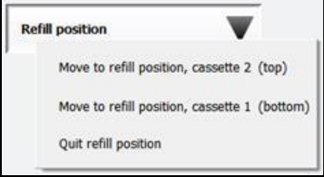
The cassettes can be changed during production. When a new setup was downloaded from
SIPLACE Pro, the operator moves the cassettes one after the other in refill position and changes
the cassettes via the station software GUI under Setup – Single feeder - Settings.
Figure 11-11: Refill position
After having changed the cassettes, the operator must click the Quit refill position button. This
triggers the SIPLACE JTF-ML2 to read the required cassette data from the inserted cassettes. The
station software receives this information and transmits the data to ASM Setup Center. If the wrong
cassette type is inserted, a corresponding error message is displayed.
The station software GUI has been enhanced to display the SIPLACE JTF-ML2 data under Manual
operations – Setup location – Selected feeder – Details…