SIPLACE Station Software 7xx to 714 介绍.pdf - 第232页
Station Software 7xx to 714.0 (R20-2) / Feature Description 11/2020 Edition 232 For diagnostic purposes, a view h as been added to the Event tool. For each "The Hermes Standard" end-point, a tab page i s displa…
Station Software 7xx to 714.0 (R20-2) / Feature Description 11/2020 Edition
231
12 Feature Description – Station Software V711.x
Features (V711.0 (R17-2): Compatible Mode 710.2)
12.1 "The Hermes Standard" – New Communication Protocol
Compatible mode: Partly compatible
"The Hermes Standard" is a new communication protocol for SMT assembly lines that can be used
alternatively to the electrical SIPLACE SMEMA interface. With this protocol, more information can
be transferred with the board down the line like unique board Ids, barcodes, conveyor speed, board
length / width / thickness. All this information can be transferred down the complete line, without
any interruption. Up to now, this was only possible within a SIPLACE SMEMA cluster. If all devices
in the line support "The Hermes Standard", whispering down the line is possible within "The
Hermes Standard" cluster as it is within the SIPLACE SMEMA cluster.
"The Hermes Standard" is supported on the X-series S, TX-series and TX micron-series placement
machines.
The sequence of machines and devices (SIPLACE, ASYS, others) must be configured in SIPLACE
Pro so that every machine / device in the production chain knows about its next and previous
device per transport lane including their according IP-addresses.
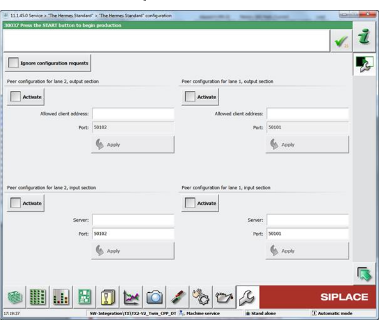
The hardware options (activate peer, host, IP address) related to "The Hermes Standard" can be
configured on the station software GUI in the "The Hermes Standard" configuration dialog under
Service – Configure machine – "The Hermes Standard".
Figure 12-1: "The Hermes Standard" configuration dialog
Station Software 7xx to 714.0 (R20-2) / Feature Description 11/2020 Edition
232
For diagnostic purposes, a view has been added to the Event tool. For each "The Hermes
Standard" end-point, a tab page is displayed, listing the received and sent messages. Only the last
100 messages after the GUI started are displayed.
If all devices between the first and the last SIPLACE station use "The Hermes Standard",
whispering of the station-wise download is supported even if 3
rd
-party equipment is setup in
between the SIPLACE devices. The user only has to confirm the changeover at the first SIPLACE
station but no longer at the SIPLACE station after the AOI system.
Restrictions
– No support for stations with shuttle.
– No support for devices with IPv6 addresses.
12.2 New Placement Force – Very Low Force in Placement, Pickup and
Dipping Processes
Compatible mode: Hidden
The new very low placement force (0.5 N) for pickup, placement and dipping is supported by the
station software. The very low force state must be set in SIPLACE Pro and can be enabled for the
following placement heads: C&P20 M2, C&P20 P and (from R18-1) C&P20 P2.
All segments of the concerned placement heads will be measured when the first board enters the
machine to check which segments are able to handle this hardware requirement. The results are
displayed in the new Very low force column of the list in which the height values of the nozzles are
displayed (Manual Operations – Subsystems – Gantry n –x Head – Segments – Height
values).
Additionally, the measurement can be performed in the Maintenance view under Test bench
inspection with the measurement step Z axis movement.
12.3 SEMO CRF80 – New Tape Feeder
Compatible mode: Hidden
The new SEMO CRF80 tape feeder from the SEMO company is supported by the station software
and occupies seven tracks on the X-table. The feeder is distributed directly by the manufacturer.
12.4 SIPLACE TX micron-Series – Teaching
Compatible mode: Complete
The station software provides a function to teach the distance between standard stop position and
light barriers of the vacuum tooling of a TX micron placement machine. The light barrier is modelled
as backward stopper. The position of this backward stopper is provided as teachable position and
can be taught like the standard forward stopper ("teaching the reference corner"). Instead of
teaching the front right corner of the board, the back corner to the right is used to teach the
backward stopper.
The default value of the distance between standard stopper and backward stopper is substituted by
the measured value.
Station Software 7xx to 714.0 (R20-2) / Feature Description 11/2020 Edition
233
12.5 Unique Machine Data for Quality Check
Compatible mode: Complete
Machine data may only be restored on the corresponding machine. Thus, the stored data contains
the machine ID which is compared to the machine's ID before restoring the machine data. Only
when the IDs match each other, the data can be used on the machine.
This way it can be prevented that wrong data is used by mistake (e.g. after changing the station
computer) and the machine might produce inaccurately using wrong calibration data.
12.6 Enhanced Machine Endurance Run
Compatible mode: Complete
The following changes and enhancements have been made for the machine endurance run:
● The machine endurance run has been moved from Manual Operations to the Maintenance
view.
● The machine endurance run has been enhanced by endurance run cycles for three new
subsystems:
– Feeder locking
– Nozzle changers
– Pin picker
The additional subsystems will be performed in each third endurance cycle.
The Feeder locking endurance run cycle will lock and unlock all feeders on all tables.
This endurance run will take place each third endurance run cycle, starting with the second
cycle.
If an error occurs, a warning is displayed but the entire endurance run will not stop. In further
cycles, the feeder endurance run will no longer be performed.
The Nozzle changer endurance run cycle will open and close each nozzle changer carrier one
after the other. This endurance run will take place each third endurance run cycle, starting with
the first cycle.
If an error occurs, a warning is displayed but the entire endurance run will not stop. In further
cycles, the nozzle changer endurance run will no longer be performed.
The Pin picker endurance run cycle will let a pin picker pick a pin from the calibration garage
of a calibrated magazine and place it back to the same position. Thus, the operator must
ensure that a pin is available there. This will be checked before the endurance run starts (after
magazine scanning). If this precondition is not fulfilled, the pin picker will be no part of the
endurance run.
This endurance run will take place each third endurance run cycle, starting with the third cycle.
If an error occurs, the entire endurance run will stop.
● An optional endurance run can be started before starting the calibration or after successful
calibration in the Automatic calibration view.
In both cases the Machine reference run is performed.
The duration of the endurance run before and after calibration can be configured
independently. The range of values of both input fields is: 0 - 100 hours.
Default for endurance run before calibration: 1 hour.
Default for endurance run after calibration: 100 hours.