SIPLACE Station Software 7xx to 714 介绍.pdf - 第238页
Station Software 7xx to 714.0 (R20-2) / Feature Description 11/2020 Edition 238 Figure 12 -2: Activities – Dipping area Additionally, the operator c an assemble and disasse mble the Linear Dipping Unit 2 X by using the r…
Station Software 7xx to 714.0 (R20-2) / Feature Description 11/2020 Edition
237
Nozzle type
Placement head
Camera type
4335
C&P20 P
C&P20 M2
SST49
6335
C&P20 P2
SST49
4235
C&P20 P
C&P20 M2
all other camera types
6235
C&P20 P2
all other camera types
12.14 SIPLACE SmartFeeder Xi – New X-Feeders
To support the high placement performance of the SIPLACE C&P20 P2 placement head, new X-
feeders have been introduced: SIPLACE SmartFeeder Xi 4 mm, 8 mm and 2 x 8 mm.
These feeders are compatible with the correspondent previous SmartFeeder X-feeders. The feeder
types remain unchanged in the software. However, their maximum performance depends on the
placement head that uses the feeder.
Using a SIPLACE SmartFeeder X together with the SIPLACE C&P20 P2 placement head may lead
to decreased placement performance since the SIPLACE SmartFeeder Xi provides optimizations
that only work together with this placement head. In other situations, both feeders behave identical.
12.15 Linear Dipping Unit 2 X – New Dipping Module
Compatible mode: Compatible
The station software supports the new Linear Dipping Unit 2 X that exists in two variants:
– Linear Dipping Unit 2 X for X-tables
– Linear Dipping Unit E for E-tables on E-series machine only
The Linear Dipping Unit 2 X can be used alternatively to the existing Linear Dipping Unit X and set
up physically wherever the existing SIPLACE Pro setup requires the former model, with one
exception: it cannot be used at the SWS.
The Linear Dipping Unit 2 X can be inserted fully assembled or not assembled on the changeover
table.
The Linear Dipping Unit 2 X needs a reference run and the flux medium a warm-up cycle process.
After the reference run, the operator must check that the dipping module is fully assembled, fill the
dipping module with flux medium and start the warm-up cycle process. Thereafter, the Linear
Dipping Unit 2 X is ready for production in the station software.
The number of squeegee cycles for the warm-up cycle (default: 30) and the squeegee speed
(default 200 mm / s) must be specified in SIPLACE Pro and will be transmitted to the station
software.
The Linear Dipping Unit 2 X is completely operated via the station software GUI in the feeder
Setup view. The following activities can be performed in the Dipping area and Planarity tabs of
the Feeder settings:
– Starting a squeegee cycle
– Starting a warm-up cycle
– Starting a reference run
– Adjusting and checking the planarity of the dip plate
Station Software 7xx to 714.0 (R20-2) / Feature Description 11/2020 Edition
238
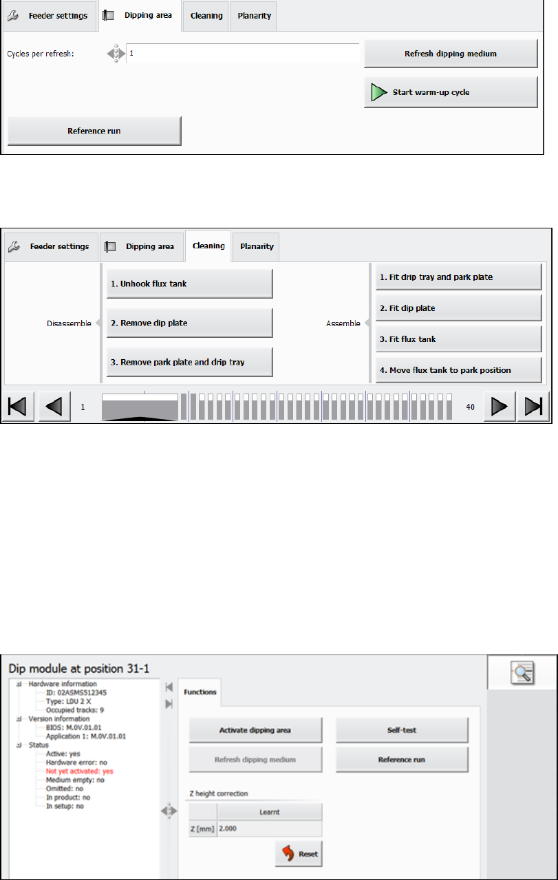
Figure 12-2: Activities – Dipping area
Additionally, the operator can assemble and disassemble the Linear Dipping Unit 2 X by using the
respective options in the Cleaning tab of the Feeder settings.
Figure 12-3: Assembling / disassembling the Linear Dipping Unit 2 X
These buttons can be pressed at any time when the production is stopped. However, they should
be executed in the order from top to bottom.
Under Manual Operations, the following activities can be performed:
– Activating the dipping area.
This function can be used if the warm-up process has already been performed, e.g. after a
restart of the station software.
– Refreshing the dipping medium (optionally multiple times)
– Starting a self-test
– Starting a reference run
Figure 12-4: Activities – Manual Operations
Error messages related to the Linear Dipping Unit 2 X are displayed on the station software GUI
and, if necessary the machine is stopped.
Detailed information on the Linear Dipping Unit 2 X can be found in the Linear Dipping Unit 2 X
User Manual, item no. [00198517-xx].
Station Software 7xx to 714.0 (R20-2) / Feature Description 11/2020 Edition
239
12.16 Adjusting Z-Height of Vacuum Tooling
Compatible mode: Complete
The new conveyor in the SIPLACE CA4 V2 placement machine uses a motor driven lifting table. To
lift the vacuum tooling to the placement z-level, the conveyor control software determines the
correct z-height and moves the lifting table to this z-height. For this purpose, a measurement
sequence has been implemented that measures the actual height, aligns it with the expected
height, and, if necessary, sends a correction value to the conveyor control.
The transport control software uses two different offsets to correct the z-height of the vacuum
tooling: standard offset and mapping offset. The standard offset is used for boards with a thickness
<= 4.5 mm. The mapping offset is used for boards with a thickness > 4.5 mm, e.g. the mapping
board.
The station software provides four touchdown positions on the vacuum tooling surface to be used
for the height measurement. Those positions are available either in the four corners or on the main
axes through the center of the vacuum tooling surface.
Some settings can be made in the Service tool. This tool has been modified as follows:
– The standard offset is determined if Vacuum tooling calibration is selected under Automatic
calibration. The board thickness must be entered manually (additional parameter Height of
board). The conveyor must be empty.
– The mapping offset is determined if Board mapping is selected under Automatic calibration.
No further entry is required.
– The (X, Y) touchdown points have been added to the conveyor section under Teaching
machine positions.
– Under Conveyor Configuration in the Vacuum tooling configuration, the user can enter for
which board thickness the adapter plate has been assigned. This facilitates the leveling.
Currently, there are two thicknesses: 1.2 mm and 0.55 mm.
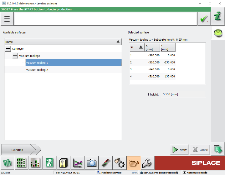
In the Maintenance tool, the Leveling assistant button has been added under Verification. By
clicking this button, the new Leveling assistant view opens.
Figure 12-5: Leveling assistant view