SIPLACE Station Software 7xx to 714 介绍.pdf - 第240页
Station Software 7xx to 714.0 (R20-2) / Feature Description 11/2020 Edition 240 The leveling assistant help s the user to adjust the z-height of t he vacuum tooling. Additionall y, this tool is used to set up the plan ar…
Station Software 7xx to 714.0 (R20-2) / Feature Description 11/2020 Edition
239
12.16 Adjusting Z-Height of Vacuum Tooling
Compatible mode: Complete
The new conveyor in the SIPLACE CA4 V2 placement machine uses a motor driven lifting table. To
lift the vacuum tooling to the placement z-level, the conveyor control software determines the
correct z-height and moves the lifting table to this z-height. For this purpose, a measurement
sequence has been implemented that measures the actual height, aligns it with the expected
height, and, if necessary, sends a correction value to the conveyor control.
The transport control software uses two different offsets to correct the z-height of the vacuum
tooling: standard offset and mapping offset. The standard offset is used for boards with a thickness
<= 4.5 mm. The mapping offset is used for boards with a thickness > 4.5 mm, e.g. the mapping
board.
The station software provides four touchdown positions on the vacuum tooling surface to be used
for the height measurement. Those positions are available either in the four corners or on the main
axes through the center of the vacuum tooling surface.
Some settings can be made in the Service tool. This tool has been modified as follows:
– The standard offset is determined if Vacuum tooling calibration is selected under Automatic
calibration. The board thickness must be entered manually (additional parameter Height of
board). The conveyor must be empty.
– The mapping offset is determined if Board mapping is selected under Automatic calibration.
No further entry is required.
– The (X, Y) touchdown points have been added to the conveyor section under Teaching
machine positions.
– Under Conveyor Configuration in the Vacuum tooling configuration, the user can enter for
which board thickness the adapter plate has been assigned. This facilitates the leveling.
Currently, there are two thicknesses: 1.2 mm and 0.55 mm.
In the Maintenance tool, the Leveling assistant button has been added under Verification. By
clicking this button, the new Leveling assistant view opens.
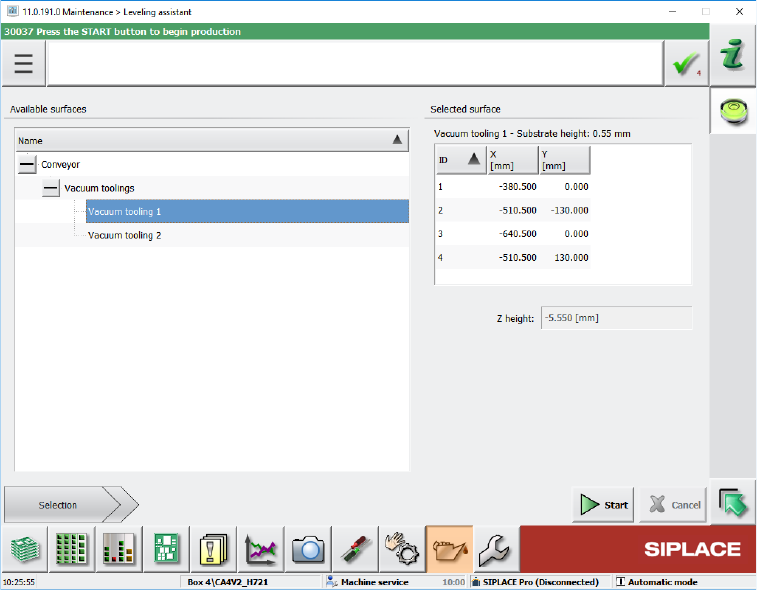
Figure 12-5: Leveling assistant view
Station Software 7xx to 714.0 (R20-2) / Feature Description 11/2020 Edition
240
The leveling assistant helps the user to adjust the z-height of the vacuum tooling. Additionally,
this tool is used to set up the planarity of the vacuum tooling surface and adjust it vertical to the
z-axes of the placement heads.
To the left, all available surfaces are displayed in a tree view. Currently, it contains entries for
adjusting the z-height of the vacuum tooling and measuring the height of the conveyor rail.
By selecting one of the available surfaces, a short description of the surface and a list of the
positions where the z-height will be measured are displayed to the right. The positions have the
same names as those that are used when the machine positions are taught. This makes it
easier for the user to identify the position in case it must be taught or if the user e.g. wants to
check that the position is on the surface and not directly above a hole.
The measurement is started by pressing the Start button. If the measurement is successful, the
Measured values are displayed automatically. Otherwise an error message is displayed.
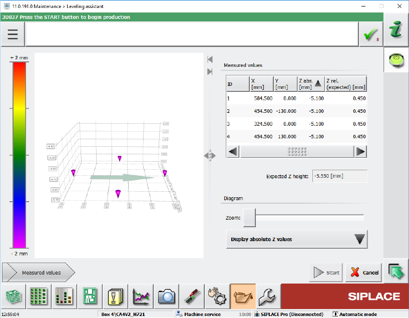
Figure 12-6: Measured values
In this view the measurement can be repeated at any time by pressing the Start button again.
An image displays the surface at the mean z-value, allowing the user to see which positions
are below or above the mean value. The user can select if the chart shall display absolute or
relative values. The relative values are always relative to the mean z-value.
12.17 SIPLACE JTF-ML2 – Enhanced Functionality
The functionality has been enhanced for the SIPLACE JTF-ML2 tray feeder. The Manual
operations dialog for the feeder has been changed as follows:
– Functions dialog
Reset buttons have been added to the existing Transfer position – Teach position and Refill
position – Teach position functions for the lifting axes to reset the respective position to the
factory settings.

Station Software 7xx to 714.0 (R20-2) / Feature Description 11/2020 Edition
241
– New I/O ports dialog
The dialog displays the input and output states of the sensors. This dialog is only visible as of
activity level Machine service.
Additionally, the endurance run for trays has been added to the Maintenance – Endurance run
dialog for the SIPLACE JTF-ML2 feeder.
NOTICE
Manual functions are not prevented with components in the tray feeder. There is no
check in the station software. The operator is responsible for whether the tray feeder is
empty or not.
12.18 Multiple Road Runner Feeders – Improved Handling
A new behavior has been implemented to improve the performance and minimize the waiting time
for multiple Road Runner feeders set up on one table.
An attribute has been added to this feeder type in SIPLACE Pro, containing one of the following
pickup strategies:
– Pickup as specified by the optimization, i.e. pickup from one Road Runner feeder until it has no
more prepared components.
– Preferring available feeders / levels, i.e. if one Road Runner feeder must prepare components,
pickup from the other Road Runner feeder until this has to prepare components.
The respective pickup strategy will be explicitly switched on with the download data of SIPLACE
Pro at the station. The placement order will not be affected.
12.19 "The Hermes Standard" – Board Locking Process
A board locking process has been introduced for lines using the "The Hermes Standard". This
means that a board in the previous machine may be locked after barcode reading and not moved
into the placement machine using "The Hermes Standard" until the board is unlocked, e.g. by the
BoardGateKeeper.
If "The Hermes Standard" is active and a barcode exists, the board remains in the previous
machine. If no barcode is available, the board remains either in the input section or in the
placement area depending on where the barcode is read.
The BoardGateKeeper (or any client that can lock the board) can now apply one of the following
behaviors:
– The board is moved into the machine and gets placed.
– The board remains in the previous machine and must be removed from there.
– The board is aborted and moved to the end of the line.
If the board is locked, a Detailed Error will be displayed as a warning.
The lock cause is displayed (e.g. invalid barcode, no BoardGateKeeper reaction) and the operator
can select one of the following actions:
– Release lock, move board into machine and cancel board
– Release lock and process board as usual