SIPLACE Station Software 7xx to 714 介绍.pdf - 第246页
Station Software 7xx to 714.0 (R20-2) / Feature Description 11/2020 Edition 246 – Free garages are need ed The operator will see how many a nd where the free garages are n eeded. There are two possible solutions: either …
Station Software 7xx to 714.0 (R20-2) / Feature Description 11/2020 Edition
245
Pin-in-Paste Height Check for TH and CPP Placement Heads
The Pin-in-paste height check is supported for the TH and CPP placement heads. The
functionality is the same as for the existing height measurement in the Snap-In detection for the
Twin VHF placement head, but the components have centering pins instead of board locks.
Restrictions
– Not supported on SIPLACE CA4 and CA4 V2 placement machines.
– Only supported together with station software version >=712.0. If the line does not contain any
station with station software >=712.0, the feature is ignored, and a warning displayed.
Increased Placement Force for TH Placement Head
The placement force has been increased to maximum 30 N for the TH placement head.
Restrictions
– Not supported on SIPLACE X-Series placement machines.
Automatic Illumination Adjustment
If an odd shape component (type Non-standard or Connector) cannot be recognized sufficiently
during teaching at the station or Vision Teach Station, an automatic illumination adjustment can be
performed. For this, the new Start optimization button must be selected in the Set component
position for optimization dialog of SIPLACE Vision.
13.4 CPP Placement Head – Increased Placement Force and
Component Weight
The placement force has been increased to maximum 15 N for the CPP placement head. The
component weight has been increased to 20 g in Pick&Place mode.
13.5 Smart Pin Support – Enhancements
13.5.1 Smart Pin Support for SIPLACE TX V2-Series
Compatible mode: Hidden
The automatic Smart Pin Support option is supported for the SIPLACE TX V2-series placement
machines with two gantries – TX2 V2 and TX2 V2i. The fixed Smart Pin Magazine occupies the
tracks 1-6 on a new table type. As default, five pins per lane are required. Optionally, an additional
pin magazine can be put on the station and up to ten pins set per lane. The Smart Pin Magazine
can be locked and unlocked in the Manual Operations view for the location.
The first nozzle magazine(s) of the nozzle changer on the left side cannot be used.
When a job with pins is downloaded to the station, the station verifies if the pins can be placed on
all programmed positions. In case the pins cannot be placed (e.g. because of screws in the lifting
table), an error message is displayed that informs the operator why the job cannot be accepted.
During the production specification, following new detailed errors may occur:
– Calibration garage is not empty
The operator must empty the calibration garage.
– Support pin for automatic calibration is missing
The operator must insert a support pin in the placement head.

Station Software 7xx to 714.0 (R20-2) / Feature Description 11/2020 Edition
246
– Free garages are needed
The operator will see how many and where the free garages are needed. There are two
possible solutions: either the pins are removed manually from the garages or free garages are
made available by inserting a pin feeder.
– Support pins are needed
The operator will see how many and where the support pins are needed. There are two
possible solutions: either the pins are inserted manually in the garages or support pins are
made available by inserting a pin feeder.
In the Preventive Maintenance view, all pins can be removed automatically from the lifting table
by clicking the button Prepare for manual maintenance.
13.5.2 Prompt To Fill Or Empty Magazines / Garages
Whenever necessary, a detailed error will be displayed prompting the operator to fill or empty the
magazines / garages. This applies to all pin magazines (W5, Q10, L10 and T5) on all placement
machines series using Smart Pin Support.
13.6 Linear Dipping Unit 2 X / Linear Dipping Unit E – Enhancements
Compatible mode: Hidden
From this station software version, multiple cavity depths (max. five) can be used on the same
dipping plate. Optionally, the dip module can be equipped with a flux level sensor.
Detailed information on the functionality of the Linear Dipping Unit 2 X and Linear Dipping Unit E
can be found in the respective User Manuals SIPLACE Linear Dipping Unit 2 X, item no.
[00198517-xx] and SIPLACE Linear Dipping Unit E, item no. [00198521].
13.7 Shuttle Extension for SIPLACE SX V2-Series
Compatible mode: Hidden
The Shuttle Extension for SIPLACE TX-series is also supported for the SIPLACE SX V2-series
placement machines.
13.8 SIPLACE MeasuringFeeder X
Compatible mode: Hidden
The station software supports the new SIPLACE MeasuringFeeder X with which the electrical
characteristics of a component can be measured. The respective attributes and additional
information such as treatment of used components must be specified in SIPLACE Pro.
The measurement will be performed at each detected component change, e.g. after a refill or splice
operation, a foil torn error, the first setup at the machine or a new feeder setup.
The MeasuringFeeder X must be set up manually and occupies one track on the X-table.
Components that were marked for measurement are automatically measured during production
following the rules that were defined during production planning.
NOTICE
The operator must ensure that the component is available for measurement!
Station Software 7xx to 714.0 (R20-2) / Feature Description 11/2020 Edition
247
Information on the MeasuringFeeder X, such as counter values and feeder ID can be accessed
under Manual Operations. The counters are used for wear evaluations of the contact module. A
button for a self-test is also offered. During the self-test, the internal wiring of the feeder and the
basic function of the measuring board are checked.
All measurements and options related to the measuring feeder are displayed in an own
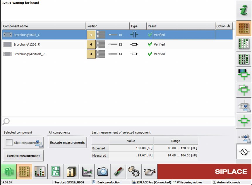
Measurement unit setup view.
Figure 13-1: Setup view for MeasuringFeeder X
In this dialog, the state of the planned component measurements can be checked.
When a row in the list is selected, the expected value and tolerance range from the last
measurement are displayed. The expected value is always displayed, even if a measurement
failed.
If the measurement is out of tolerance, a detailed error is displayed and the respective track
disabled. The user can decide to execute a manual measurement for the selected component or to
skip the measurement. For skipping the measurement, the Advanced production activity level is
required.
The measured values of the reference component of one package will be recorded in the trace
data. Each subsequent component from the package has this information attached. If a
measurement failed, the result will also be attached to the package, even if no component will be
picked up afterwards.
By clicking the Generate report button, a report of the measured components is generated in an
HTML file. The report contains the measured value and the expected value of the components and
the feeder ID.
Detailed information on the MeasuringFeeder X can be found in the SIPLACE Measurement
Feeder X User Manual, item no. [00198526-xx].