SIPLACE Station Software 7xx to 714 介绍.pdf - 第254页
Station Software 7xx to 714.0 (R20-2) / Feature Description 11/2020 Edition 254 By clicking the Select all steps that have to be done button, all calibration steps that mu st be performed are selected an d also the locat…
Station Software 7xx to 714.0 (R20-2) / Feature Description 11/2020 Edition
253
Explanation of the states
Icon
State
Calibration has been successfully performed
Calibration has not been performed
Calibration must be performed again because of a dependency to another calibration
item (i.e. if board mapping is executed, the head mapping should also be performed)
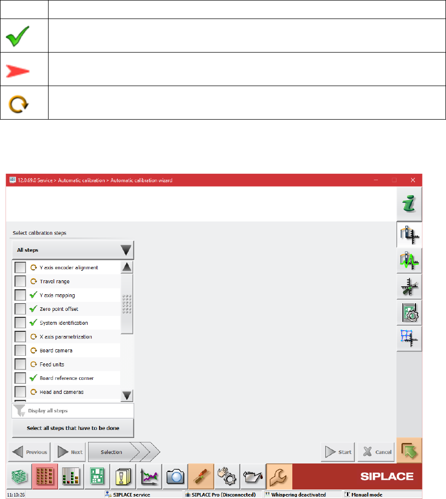
Automatic calibration wizard
Figure 13-5: Automatic calibration wizard
The second new view is intended for executing the calibration steps and consists of three pages.
The first page of the wizard lists the calibration steps and their states but no locations. The
contents of the list can be different depending on the user choice done through the button above
the list. The user choice will be stored. There are three possible choices:
– Combined steps: The offered steps are combined steps, they represent common tasks and
give a quick access to them.
– All steps: All calibration steps are in the list. The user can select every step to be executed.
– Single steps only: The steps that are not part of combined steps are displayed. Thus, the user
can quickly access steps like Bulkfeeder X, Vacuum tooling, etc.
There is no check if the user steps are compatible to each other and no automatic selecting of
other steps.
Station Software 7xx to 714.0 (R20-2) / Feature Description 11/2020 Edition
254
By clicking the Select all steps that have to be done button, all calibration steps that must be
performed are selected and also the locations where the calibration must be performed.
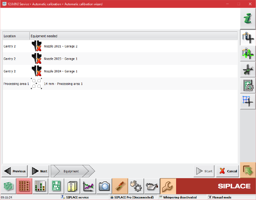
On the second page of the wizard the required equipment for the selected steps is displayed.
Figure 13-6: Required equipment
The third page of the wizard is reserved for preparation steps and will only be displayed if
preparation steps are needed, i.e. for mapping.
Station Software 7xx to 714.0 (R20-2) / Feature Description 11/2020 Edition
255
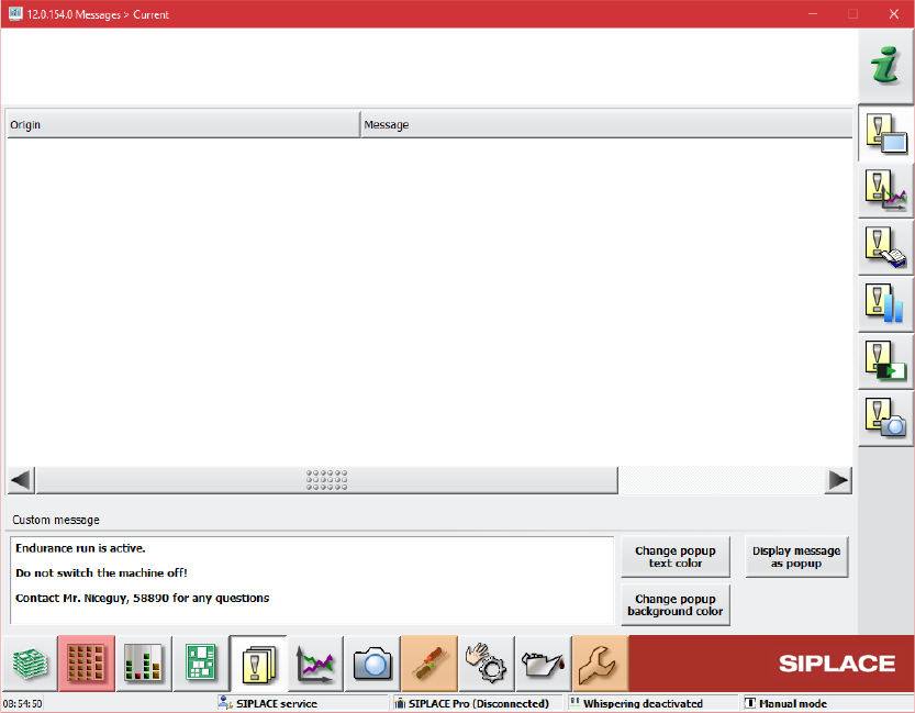
13.14 Displaying Customer Messages
The operator of the station software can leave a message for the next operator. Optionally, the
message can be displayed in a pop-up window.
For this, the Messages – Current dialog has been extended in the Event analyzer.
Figure 13-7: Event analyzer – Messages – Current dialog
An entry field for the message text is available in the bottom part of the dialog. The message can
be displayed as a pop-up window covering a region of the application. The colors of the text and
background in the pop-up window can be set individually.