SIPLACE Station Software 7xx to 714 介绍.pdf - 第256页
Station Software 7xx to 714.0 (R20-2) / Feature Description 11/2020 Edition 256 Display message as popup option en abled: Figure 13 -8: Pop-up window enab led The pop-up window is closed whene ver it is clicked. The navi…
Station Software 7xx to 714.0 (R20-2) / Feature Description 11/2020 Edition
255
13.14 Displaying Customer Messages
The operator of the station software can leave a message for the next operator. Optionally, the
message can be displayed in a pop-up window.
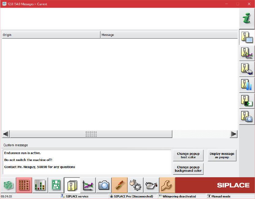
For this, the Messages – Current dialog has been extended in the Event analyzer.
Figure 13-7: Event analyzer – Messages – Current dialog
An entry field for the message text is available in the bottom part of the dialog. The message can
be displayed as a pop-up window covering a region of the application. The colors of the text and
background in the pop-up window can be set individually.
Station Software 7xx to 714.0 (R20-2) / Feature Description 11/2020 Edition
256
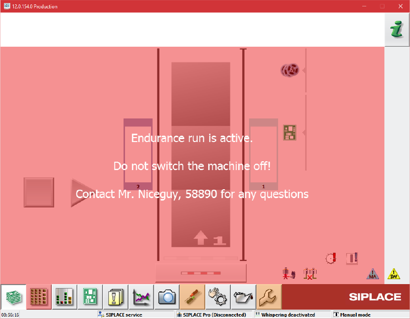
Display message as popup option enabled:
Figure 13-8: Pop-up window enabled
The pop-up window is closed whenever it is clicked. The navigation in the GUI is also possible
when the pop-up window is displayed.
13.15 SIPLACE Vision Functionality – Additional Enhancements
The main additional enhancements in SIPLACE Vision 5.6.1 are listed below.
13.15.1 Contamination Scan
Compatible mode: Hidden
SIPLACE Vision provides a new nozzle scan for customer-specific nozzles to detect contamination
by solder paste. Other defects will not be detected by this scan. The contamination check must be
configured and enabled in SIPLACE Pro and is supported for the following camera types:
SST23, SST25, SST28, SST29, SST30, SST33, SST36, SST38, SST41, SST45, SST48 and
SST49.
The scan will be performed automatically after the specified number of picked-up components per
nozzle. A manual scan can be started in the Check sensors and functions of specific
components – Head – Check vacuum, height and scan values view.
Station Software 7xx to 714.0 (R20-2) / Feature Description 11/2020 Edition
257
13.15.2 Detection of Tilted Chips
Compatible mode: Complete
The new Detection of tilted chips option can be used for component shape type CHIP. The
option is supported for camera types SST41, SST48 and SST49 and must be enabled / disabled
for each camera type in the List of measurement options.
For the detection, the component is always recorded with a second illumination (0° illumination).
The components refer to this illumination.
The more a chip is tilted, the darker the pads appear.
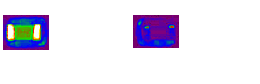
Example
Chip in normal position
Tilted chip
The metallic connections reflect the 0°
illumination into the camera. The connections
are almost visible in full width.
The metallic connections reflect the 0°
illumination to the side. The connections only
appear bright in the lateral edge of the
component
Restrictions
– Among other things, detection of the tilt depends on the brightness, shape and reflection
properties of the components. Since these properties are not strictly specified, a positive
detection of the tilt may not be generally applicable for all component manufacturers and
batches.
– When using the option with camera SST 41, the placement performance is slightly reduced.
13.15.3 Face Down Recognition with Gullwing Leads – Enhancement
Compatible mode: Compatible
The new Detection using gullwing connections with one-sided illumination option can be
selected under Choose the method to be used to detect flipped components if the following
requirements are met:
– Camera type SST48 or SST49.
– Component shape types: SOT, SOXX, QFP, Connector, Non-standard or Sockets.
– There are at least two gullwing groups, each rotated 180 degrees to each other.