SIPLACE Station Software 7xx to 714 介绍.pdf - 第259页
Station Software 7xx to 714.0 (R20-2) / Feature Description 11/2020 Edition 259 – For tape feeders: The nominal pickup position is dis played as red and dotted cros shairs in the Positions correction teaching dialog and …
Station Software 7xx to 714.0 (R20-2) / Feature Description 11/2020 Edition
258
Example
SOT23
SOT23 – Face up
SOT23 – Face down
When the face down recognition wizard is started and no other process is selected, the option will
be used automatically if the requirements mentioned above apply.
If a face down recognition has already been taught in the wizard for the current camera type with
an older Vision version, this will continue to be used by Vision version 5.6.1 if you do not explicitly
select the new option.
If the new option is selected for the current camera type with Vision version 5.6.1, older versions
continue to apply the previously set method. This also applies if the option is selected for other
camera types than SST48 or SST49 with Vision version 5.6.1.
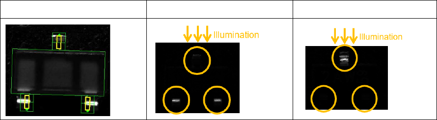
13.15.4 Flux Inspection
Compatible mode: Hidden
A new flux inspection has been introduced to check if components have been dipped or not. For
this, a reference image is captured before dipping. After dipping, the inspection compares the
current image with the reference image.
The flux inspection can be enabled in SIPLACE Pro or in the SIPLACE Vision Editor under Special
measurement options for the following component shapes:
– BGA
– Non-standard
– CCGA
The difference between dipped and not dipped components strongly depends on the color of the
flux and the appearance of the ball. A minimum ball diameter is set as default and this value will be
checked during teaching. In individual cases, you can switch off the check and test whether the flux
used can also be recognized with smaller ball diameters.
13.16 Miscellaneous Improvements and Enhancements
– Cover Lock for SX-Series Placement Machines
The existing cover lock configuration for the TX-series placement machines is supported for the
SX-series placement machines, as well. The used I/O port is named Protective cover locked
in the I/O Ports page on the GUI.
Compatible mode: Hidden
– The JTF-ML2 can be combined with the C&P20 P2 placement head on SIPLACE TX V2
placement machines.
Compatible mode: Complete
– If a nozzle is e.g. contaminated or sticky, this affects the placement reliability and may lead to
frequent pickup and Vision errors. The station software now detects such situations and
displays a corresponding detailed error. Possible solutions like cleaning, rejecting, changing the
nozzle or disabling the segment are offered.
Compatible mode: Complete
Station Software 7xx to 714.0 (R20-2) / Feature Description 11/2020 Edition
259
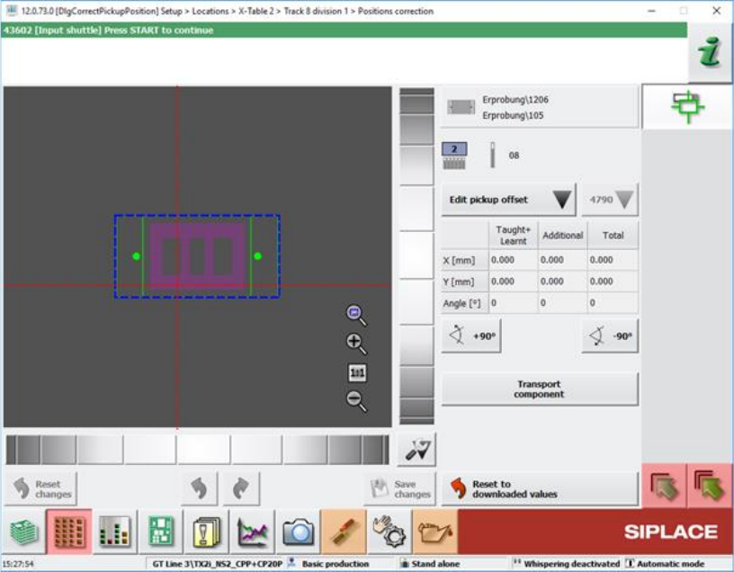
– For tape feeders:
The nominal pickup position is displayed as red and dotted crosshairs in the Positions
correction teaching dialog and the Check tape position at pickup position of track machine
function dialog.
Figure 13-9: Positions correction teaching dialog
The pickup position is determined by the current Pickup position feeder setting and the
Fiducial measurement result which may be zero if neither fiducial nor pocket recognition are
specified.
Compatible mode: Complete
– Optimized selection controls for the touch screen.
The selection of a tray inside an MTC, WPC or generic automatic tray (i.e. JTF) widget can be
done by zooming in when the user touches the widget.
Compatible mode: Complete
– Windows 10 can be used for station computers on SIPLACE SX V2 placement machines.
Station Software 7xx to 714.0 (R20-2) / Feature Description 11/2020 Edition
260
Features (V712.1 (R19-1): Compatible Mode 711.2)
13.17 OSC Package Option – Enhancements
Detailed information on the OSC Package features can be found in the OSC Package User Guide,
item no. [00198374-xx].
The main enhancements made for the OSC Package Option in the station software and SIPLACE
Vision are listed in the overview below.
Height Values for Snap-In and Pin-In-Paste Components Saved Machine-Dependently
Compatible mode: Complete
When restarting a machine, the height teaching step for snap-in / pin-in-paste components does
not need to be repeated. However, the height teaching step still needs to be repeated if attributes
of the board have been changed in SIPLACE Pro.
Placement of Critically Tall Components with Twin VHF or CPP Placement Head
Compatible mode: Hidden
It is possible to place several critically tall components. The collision typology model has been
extended to support this new feature.
The target head for critically tall components is either a CPP head in high head position or a Twin
VHF head. Which components are considered critically tall depends on the respective placement
head they are placed with.
Chipping Inspection
The component chipping detection functionality checks whether the edge of a component has
larger deviations than defined. It can be enabled or disabled using the Chipping inspection
checkbox in the Vision Inspection tab of the Component Shape Editor of SIPLACE Pro Desk.
Restrictions
– Only supported for vision types BareDie, BGA, CCGA, Chip, Moulded, Nonstandard.
– The OSC license must be available.
13.18 Robustness Package – Enhancements
Automatic Checking for Camera Soiling
Compatible mode: Complete
In Maintenance > Verification, the option Check for camera soiling has been added which can
be used to perform a check for soiled cameras.
When an illumination calibration is performed, the system will do an automatic checking for camera
soiling. If this is not desired, the automatic checking for camera soiling during an illumination
calibration can be turned off with the new option Skip check for soiling of all cameras in
Maintenance > Verification > Calibrate illumination.
Restrictions
– The check for camera soiling is implemented for the camera types SST23, 28, 29, 30, 38, 41,
45, 46, 48 and 49.