SIPLACE Station Software 7xx to 714 介绍.pdf - 第267页
Station Software 7xx to 714.0 (R20-2) / Feature Description 11/2020 Edition 267 14.12 Changes With HERMES -IPC-9852 Version 1.2 Compatible mode: Complete The station software fully complie s with HERMES-IPC-9852 V1.2. In…
Station Software 7xx to 714.0 (R20-2) / Feature Description 11/2020 Edition
266
14.8 Placement Improvements – Freely Programmable Custom Reject
Bins
Compatible mode: Complete
Additional to the already existing standard SIPLACE reject bins, it is possible to program custom
reject bins. These custom reject bins can be used to e.g. dispose of “dipped” or “glued”
components separately from other disposed components. For further information, please refer to
the Feature Guide Freely Programmable Reject Bin, item no. [00198771-xx].
The custom reject bins can be configured via an individual XML file. It is also possible to disable
standard reject bins using this XML file.
WARNING
Risk of crashing
If the custom reject bin is not installed correctly and the highest edge of the customer
reject bin exceeds the z-height of the conveyor edge, a crash might occur.
► Make sure the custom reject bin is correctly installed!
It is not possible to use a safety circuit to check whether the custom reject bin is fit
correctly into the machine.
14.9 Placement Improvements – Automatic Pin1 Recognition
Compatible mode: Complete
To save time during placement, it is possible to limit the check period and check frequency per
component for the orientation check during position check.
For this, the Check pickup orientation on component change option in the Object Properties of
the Component Editor in SIPLACE Pro has been extended. If this option is activated, the check
mode can be set to either Manually by user or to Automatic. If the Automatic mode is selected,
three further options can be specified: the number of measurements, the checking period, and the
check sequence.
For further information, please refer to the Feature Guide Automatic Pin1 Recognition, item no.
[00198770-xx].
14.10 Reject Rate View - Enhancements
Compatible mode: Complete
The reject rate view per location has been extended by an additional widget which displays the
number and kind of errors on a daily or hourly basis. The reject rate view can be accessed via
Messages - Statistics.
14.11 Changes for Stop Thresholds for Reject Rate Monitoring
Compatible mode: Complete
The “track empty” errors are no longer resettable on the station GUI. Instead, an error message is
displayed which can only be cleared by Machine Service, i.e. the pickup settings checked option
on the error to clear the message is deactivated for Operator and Advanced production.

Station Software 7xx to 714.0 (R20-2) / Feature Description 11/2020 Edition
267
14.12 Changes With HERMES-IPC-9852 Version 1.2
Compatible mode: Complete
The station software fully complies with HERMES-IPC-9852 V1.2. In order to visualize the Vertical
Channel messages, the Vertical channel tab has been added to the IPC-HERMES-9852 events
under Messages. In this tab, the traffic on the HVC (Hermes Vertical Channel) with all running
sessions and the corresponding client systems can be viewed.
14.13 New Fiducial Type “Edge” Supported
Compatible mode: Complete
The new fiducial type “Edge” is supported. With this new fiducial type, it is possible to define the
run of an edge, which is useful for LED alignments. The fiducial is visualized as a hatched line, as
shown in the following icon:
14.14 Inspecting Components After Placement at Too High Speed
Compatible mode: Complete
If the PCB description is incorrect or if there are bends in the PCB, the nominal position of the PCB
top edge might deviate distinctly. The component might therefore be placed at too high speed, and
consequently, get damaged.
If such an event occurs, the respective placement position is set to “inspect” and the error
40084 Component on board is possibly damaged is displayed. The error provides images from
the PCB camera of the component at the placement position and at the nozzle which can be used
to inspect the component for damages. The error can be solved with one of the following options:
– Component is not damaged: continue producing
– Component is damaged: skip panel
– Component is damaged: cancel board
14.15 “SIPLACE Service” Button Permanently Visible in Station GUI
The SIPLACE service button in the station GUI is now permanently available to enter the service
password. The key sequence that was previously used to open the SIPLACE service is no longer
supported.
Station Software 7xx to 714.0 (R20-2) / Feature Description 11/2020 Edition
268
Features (V713.1 (R20-1): Compatible Mode 712.3)
14.16 Adjusting Sigma Level for Accuracy Check Tool (ACT) Results
Compatible mode: Complete
The Accuracy Check Tool (ACT) is used to determine the placement accuracy of a specific
placement head and, if necessary, correct it. If an ACT check is performed, components are
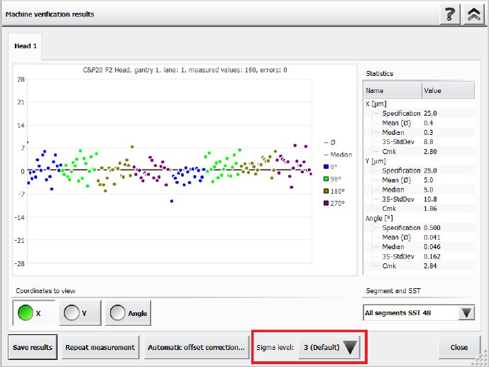
measured after placement and the results are displayed in the Machine verification results
dialog.
It is now possible to adjust the sigma level in this Machine verification results dialog via the new
Sigma level drop-down list. The selectable sigma levels in the list range from the configured
default value (usually 3 or 4) up to maximum level 6.
Figure 14-2: Adjusting the sigma level in the ACT Results dialog
If a new measurement is done, the results in the Machine verification results dialog are displayed
according to the default sigma level value that has been configured for the station. When you
change the sigma level, the results within the Machine verification results dialog are refreshed
accordingly. Additionally, the +/- specification values for X, Y and Angle are listed in the statistical
results on the right side of the dialog.
When generating a PDF report, the statistical data in the PDF matches the sigma level that has
been selected when the PDF report has been generated. You can change the sigma level after
generating a PDF report, but please note that if you want to generate a new PDF report with the
new sigma level, you need to repeat the measurement.
The general ACT behavior is not changed by this enhancement, i.e. the values for the offset
correction are independent from the selected sigma level. To repeat the manual correction, a new
ACT placement is needed.
For further information on ACT, please refer to the ACT User Manual, item no. [00196351-xx].