SIPLACE Station Software 7xx to 714 介绍.pdf - 第269页
Station Software 7xx to 714.0 (R20-2) / Feature Description 11/2020 Edition 269 14.17 Support of SIPLACE TX2 V2 HD / SIPLACE T X2i V2 HD The hardware upgrade kit High Density option package TX, item no. [588510- xx] for …
Station Software 7xx to 714.0 (R20-2) / Feature Description 11/2020 Edition
268
Features (V713.1 (R20-1): Compatible Mode 712.3)
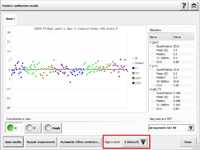
14.16 Adjusting Sigma Level for Accuracy Check Tool (ACT) Results
Compatible mode: Complete
The Accuracy Check Tool (ACT) is used to determine the placement accuracy of a specific
placement head and, if necessary, correct it. If an ACT check is performed, components are
measured after placement and the results are displayed in the Machine verification results
dialog.
It is now possible to adjust the sigma level in this Machine verification results dialog via the new
Sigma level drop-down list. The selectable sigma levels in the list range from the configured
default value (usually 3 or 4) up to maximum level 6.
Figure 14-2: Adjusting the sigma level in the ACT Results dialog
If a new measurement is done, the results in the Machine verification results dialog are displayed
according to the default sigma level value that has been configured for the station. When you
change the sigma level, the results within the Machine verification results dialog are refreshed
accordingly. Additionally, the +/- specification values for X, Y and Angle are listed in the statistical
results on the right side of the dialog.
When generating a PDF report, the statistical data in the PDF matches the sigma level that has
been selected when the PDF report has been generated. You can change the sigma level after
generating a PDF report, but please note that if you want to generate a new PDF report with the
new sigma level, you need to repeat the measurement.
The general ACT behavior is not changed by this enhancement, i.e. the values for the offset
correction are independent from the selected sigma level. To repeat the manual correction, a new
ACT placement is needed.
For further information on ACT, please refer to the ACT User Manual, item no. [00196351-xx].
Station Software 7xx to 714.0 (R20-2) / Feature Description 11/2020 Edition
269
14.17 Support of SIPLACE TX2 V2 HD / SIPLACE TX2i V2 HD
The hardware upgrade kit High Density option package TX, item no. [588510-xx] for the
SIPLACE TX2 V2 / TX2i V2 is supported.
With a conveyor update and corresponding X-Fiducials contained in the hardware upgrade kit, a
SIPLACE TX2 V2 / TX2i V2 can be remodeled to a SIPLACE TX2 V2 HD / TX2i V2 HD. These
upgraded machine types can perform high density placement.
Original Machine
Type
Placement Heads
Upgraded
Machine Type
SIPLACE TX2 V2
2x CPP placement heads
(low position) with SST30
TX2 V2 HD
SIPLACE TX2i V2
2x CP20 P2 placement heads with SST48
TX2i V2 HD
2x CP20 P2 placement heads with SST49
1x CP20 P2 placement head with SST48
+ 1x CP20 P2 placement head with
SST49 (mixed camera configuration)
Table 14-1: Overview of high density placement upgrade option per machine type
NOTICE
When upgrading a machine type, the station software needs to be reinstalled on that
machine.
Restrictions
– The new machine types do not support Smart Pin Support.
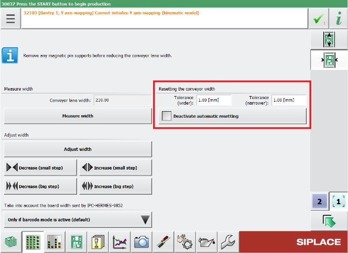
14.18 Configuring Tolerance Values for Resetting the Conveyor Width
Compatible mode: Complete
If the Automatic Width Adjustment option has been activated on the Line Control GUI and the
conveyor width of the lane differs from the width specifications in the recipe (e.g. because it has
been manually changed for maintenance), the conveyor width is automatically reset to the width
specifications from the recipe at the start of production.
But even if the Automatic Width Adjustment option is deactivated, the conveyor width is reset to
the width specified in the recipe at the start of production if the conveyor width has been manually
changed further than a configured tolerance allows.
Station Software 7xx to 714.0 (R20-2) / Feature Description 11/2020 Edition
270
The tolerance values can be specified in the Tolerance fields under Resetting the conveyor
width in the Width settings of the respective lane. If the Automatic Width Adjustment option is
deactivated on the Line Control GUI and you do not want the conveyor width to be automatically
reset at the start of production, you can use the Deactivate automatic resetting option under
Resetting the conveyor width.
Figure 14-3: Configuring tolerance values for resetting the conveyor width
By default, the conveyor width is allowed to differ by 1 mm from the width specifications in the
recipe. The smallest possible value is 0.0 mm (no deviation allowed). Negative values are not
allowed. The biggest possible value is 10 mm.
Restrictions
– The station can only adjust the width while no board is in the respective lane.
14.19 Scan Request Dialog – Enhancements
Compatible mode: Complete
When performing a scan request for a feeder, it is possible to switch between feeder divisions in
the Scan Request dialog.
After clicking the scan request button on the feeder or after ordering a scan request in ASM Setup
Center, the Scan Request dialog opens in the station GUI. In this dialog, you can navigate
between feeder divisions by clicking on the arrow buttons next to the division number.