SIPLACE Station Software 7xx to 714 介绍.pdf - 第271页
Station Software 7xx to 714.0 (R20-2) / Feature Description 11/2020 Edition 271 Figure 14 -4: Buttons for navigating between divisions in Scan Reques t dialog For easier visibility the number of the currently selected f …
Station Software 7xx to 714.0 (R20-2) / Feature Description 11/2020 Edition
270
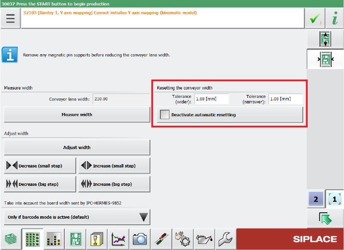
The tolerance values can be specified in the Tolerance fields under Resetting the conveyor
width in the Width settings of the respective lane. If the Automatic Width Adjustment option is
deactivated on the Line Control GUI and you do not want the conveyor width to be automatically
reset at the start of production, you can use the Deactivate automatic resetting option under
Resetting the conveyor width.
Figure 14-3: Configuring tolerance values for resetting the conveyor width
By default, the conveyor width is allowed to differ by 1 mm from the width specifications in the
recipe. The smallest possible value is 0.0 mm (no deviation allowed). Negative values are not
allowed. The biggest possible value is 10 mm.
Restrictions
– The station can only adjust the width while no board is in the respective lane.
14.19 Scan Request Dialog – Enhancements
Compatible mode: Complete
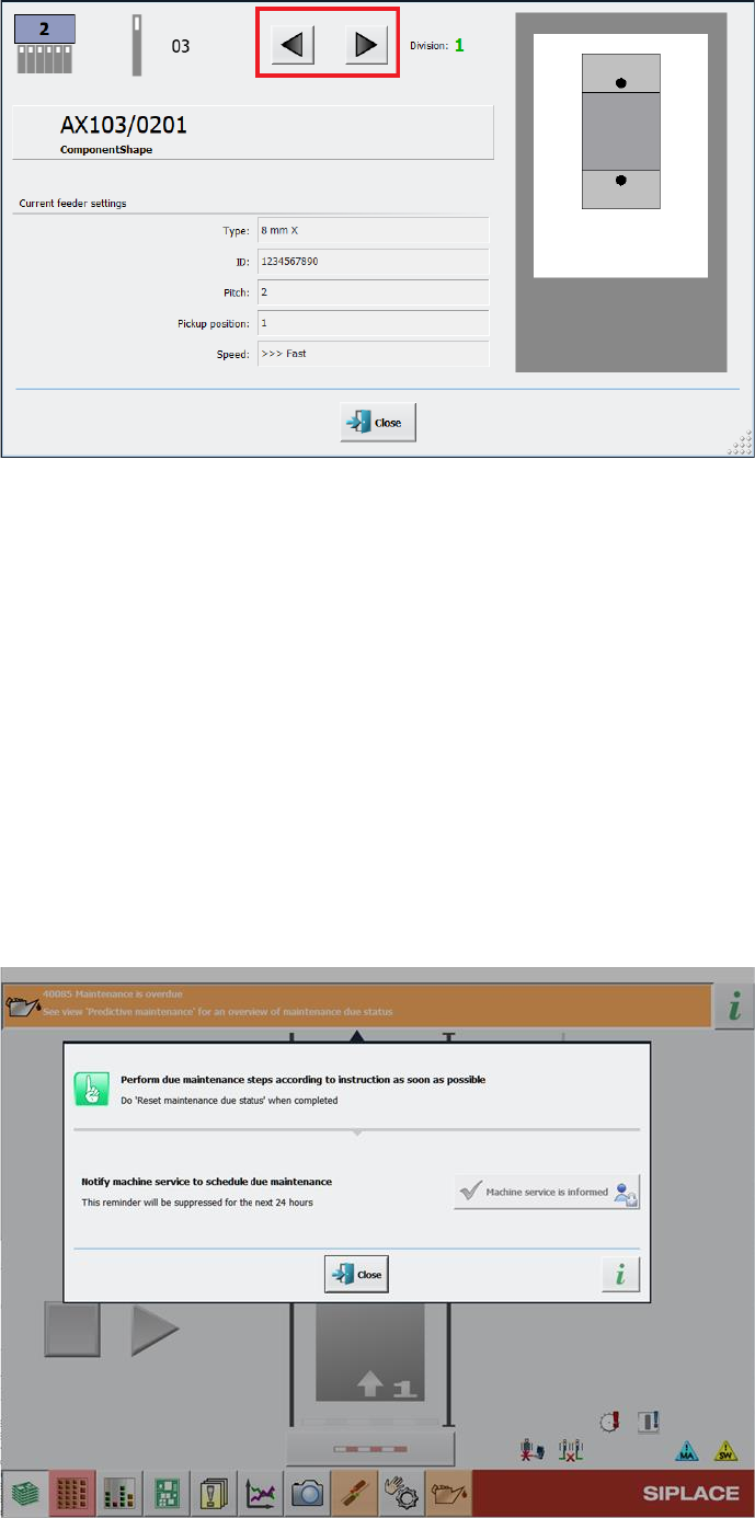
When performing a scan request for a feeder, it is possible to switch between feeder divisions in
the Scan Request dialog.
After clicking the scan request button on the feeder or after ordering a scan request in ASM Setup
Center, the Scan Request dialog opens in the station GUI. In this dialog, you can navigate
between feeder divisions by clicking on the arrow buttons next to the division number.
Station Software 7xx to 714.0 (R20-2) / Feature Description 11/2020 Edition
271
Figure 14-4: Buttons for navigating between divisions in Scan Request dialog
For easier visibility the number of the currently selected feeder division has been further
highlighted. The division number is now displayed in a bigger font in an extra field and blinks.
Restrictions
– The feature is only supported for the following feeder types that have multiple divisions or
channels:
– Smartfeeder 2x8mm Xi Splice, item no. [00141499-xx]
– Smartfeeder 2x8mm Xi, item no. [00141479-xx]
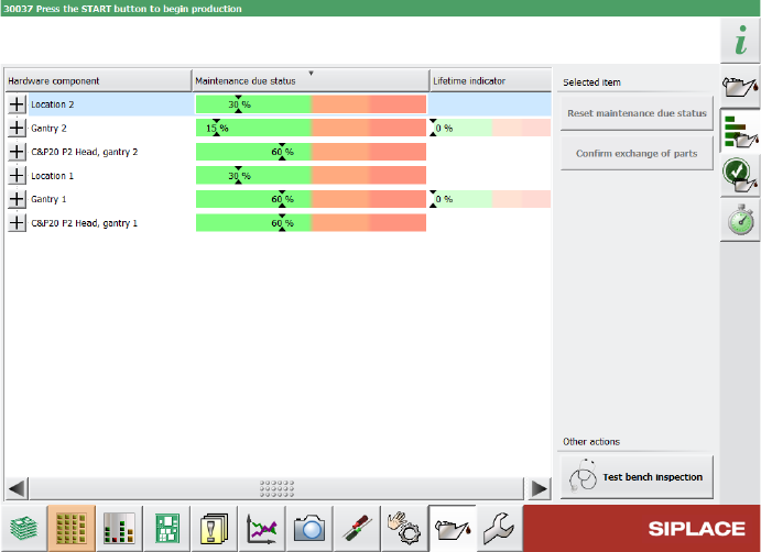
14.20 Monitoring and Logging of Maintenance Status
To improve machine availability and to prevent unplanned machine failures, hardware components
such as the guide cars, guide rails and loose bearings are monitored and, when their service life
setpoints are reached, a detailed error message is issued at the station.
Figure 14-5: Detailed error message for maintenance status
Station Software 7xx to 714.0 (R20-2) / Feature Description 11/2020 Edition
272
Furthermore, the status bar for monitoring the maintenance status of hardware components is now
divided into different color sections. If certain threshold values are exceeded, the maintenance
status in the progress bar switches to a different color.
Figure 14-6: Example for maintenance status indicated in different colors
For further information, please refer to the Technical Information about the maintenance due status
on SIPLACE machines, item no. [TI2020-03D06].
14.21 Synchronizing Recalibrations of All SIPLACE Stations Along the
Line
Compatible mode: Hidden
The recalibration procedure can now be synchronized for all SIPLACE stations along the line to
minimize the overall downtime of that line. When a recalibration is triggered, the first SIPLACE
machine in the line assumes the role of “master station”. All other reachable SIPLACE stations
along the line are then triggered to also start the same recalibration procedure as the master
station.
If a non-master SIPLACE station cannot be reached when the synchronized recalibration is
triggered, e.g. because it is offline at that specific moment, its recalibration is done unsynchronized.
If a station is triggered to start a synchronized recalibration while it is producing, the station stops
production and starts the recalibration procedures. If the station is triggered to start a synchronized
recalibration while it is already recalibrating, the triggered recalibration procedure is added to the
recalibration job queue, i.e. the recalibration procedure is done after the current recalibration
procedure is finished. If a recalibration triggered by the master station is already performed during
the currently running recalibration procedure on the station, it will not be added to the recalibration
job queue. If the station is triggered to start a synchronized recalibration while it is being stopped,
e.g. by a user or due to an error, the recalibration procedure is added to the recalibration job queue
and is done after the station has been restarted.
In the Machine neighborhood settings in the station GUI, you can view information on the
synchronized recalibration in the Recalibrations at line level area on the right. Depending on
which role the station has during the synchronized recalibration, different information is displayed.