SIPLACE Station Software 7xx to 714 介绍.pdf - 第276页
Station Software 7xx to 714.0 (R20-2) / Feature Description 11/2020 Edition 276 14.23 Selecting Flexible Fill ing Level for Matrix Trays Compatible mode: Complete In the Change filling level dialog it is possible to defi…
Station Software 7xx to 714.0 (R20-2) / Feature Description 11/2020 Edition
275
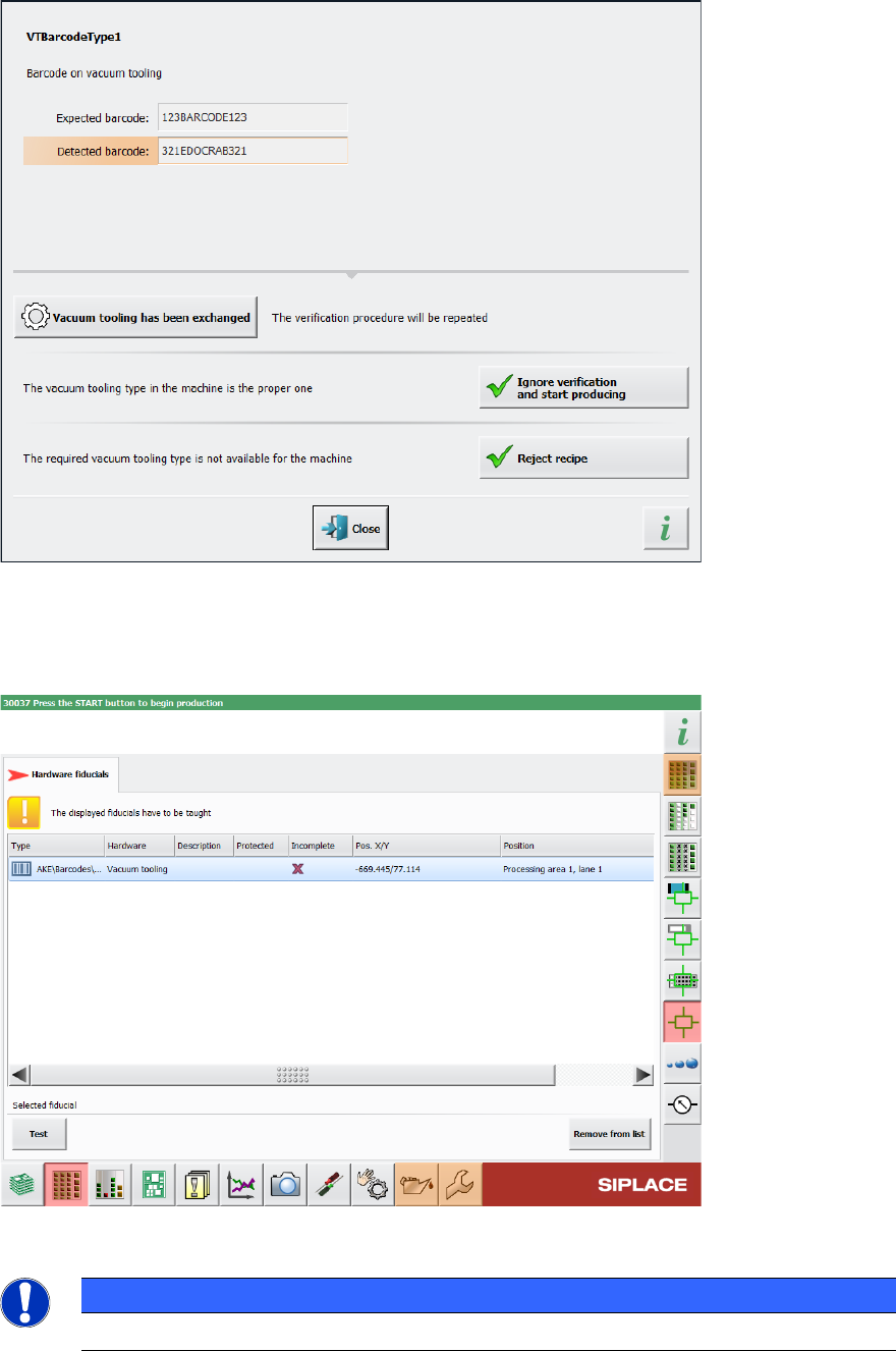
Figure 14-9: Displayed error message if barcode information does not match recipe
In the Current machine requests for teaching view in the station GUI, the Hardware fiducials
tab has been added, providing a list of hardware fiducials that must be taught. This tab also
contains the barcodes for vacuum tooling.
Figure 14-10: List of vacuum tooling barcodes that need to be taught
NOTICE
The position of the barcode cannot be changed in the station software.
Station Software 7xx to 714.0 (R20-2) / Feature Description 11/2020 Edition
276
14.23 Selecting Flexible Filling Level for Matrix Trays
Compatible mode: Complete
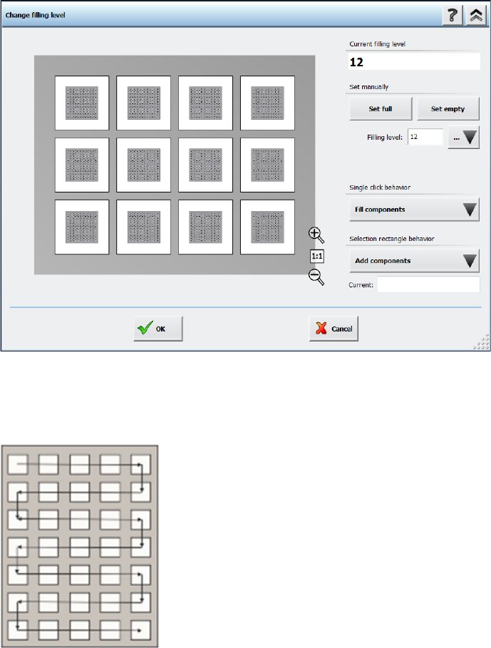
In the Change filling level dialog it is possible to define the filling level of a matrix tray more
flexibly. You can either enter the amount of components on the matrix tray in the Filling level field
or define a pick-up area with the Single click behavior option or the Selection rectangle
behavior option. A detailed description on how to use the different options can be found in the
Online Help.
Figure 14-11: Selecting filling level for matrix trays
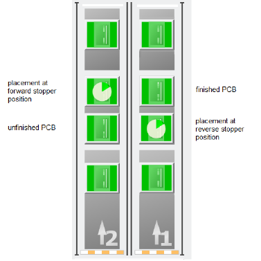
The pick-up sequence for components is fixed and moves, depending on the selected amount of
components, in a meandering fashion from the top left pocket to the bottom right pocket, as shown
in the following figure:
Figure 14-12: Pick-up sequence for components in a Matrix Tray
Station Software 7xx to 714.0 (R20-2) / Feature Description 11/2020 Edition
277
15 Feature Description – Station Software V714.x
Features (V714.0 (R20-2): Compatible Mode 713.2)
15.1 SIPLACE Tray Unit Supported
Compatible mode: Hidden
The new SIPLACE Tray Unit (STU), item no. [00520570-xx] is supported on the SIPLACE TX V2
placement machine.
15.2 SIPLACE TX2 V2 – Placement at Forward Stopper and Reverse
Stopper Supported in Convoy Mode
Compatible mode: Hidden
If the convoy mode is activated on a TX2 V2 placement machine, it is now possible to place PCBs
on either the forward stopper position or the reverse stopper position. If a PCB is to be placed at
the forward stopper position, the PCB is first held at the reverse stopper position until the
placement of the previous PCB at the forward stopper position is finished. Once the placement of
the previous PCB is finished, the PCB is moved to the forward stopper position and placed as well.
Vice versa, if the placement is to be done at the reverse stopper position, the forward stopper
position is used as a buffer position to hold the already placed PCB before moving the PCB to the
output conveyor.
Figure 15-1: Overview of placement at forward stopper and reverse stopper positions
Restrictions:
– The convoy mode cannot be used if a vacuum tooling is installed or if the PCB is longer than
175 mm.