SIPLACE Station Software 7xx to 714 介绍.pdf - 第278页
Station Software 7xx to 714.0 (R20-2) / Feature Description 11/2020 Edition 278 15.3 New Hardware Supported on SIPLACE TX2 V2 Compatible mode: Not supporte d The following hardware is sup ported on the SIPLACE TX 2 V2: –…
Station Software 7xx to 714.0 (R20-2) / Feature Description 11/2020 Edition
277
15 Feature Description – Station Software V714.x
Features (V714.0 (R20-2): Compatible Mode 713.2)
15.1 SIPLACE Tray Unit Supported
Compatible mode: Hidden
The new SIPLACE Tray Unit (STU), item no. [00520570-xx] is supported on the SIPLACE TX V2
placement machine.
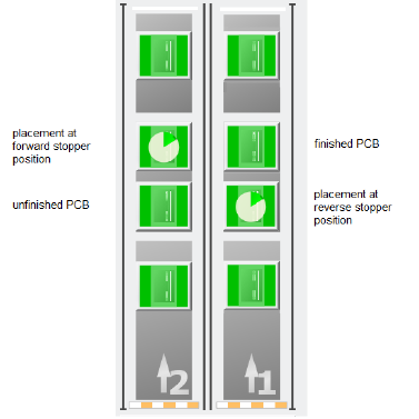
15.2 SIPLACE TX2 V2 – Placement at Forward Stopper and Reverse
Stopper Supported in Convoy Mode
Compatible mode: Hidden
If the convoy mode is activated on a TX2 V2 placement machine, it is now possible to place PCBs
on either the forward stopper position or the reverse stopper position. If a PCB is to be placed at
the forward stopper position, the PCB is first held at the reverse stopper position until the
placement of the previous PCB at the forward stopper position is finished. Once the placement of
the previous PCB is finished, the PCB is moved to the forward stopper position and placed as well.
Vice versa, if the placement is to be done at the reverse stopper position, the forward stopper
position is used as a buffer position to hold the already placed PCB before moving the PCB to the
output conveyor.
Figure 15-1: Overview of placement at forward stopper and reverse stopper positions
Restrictions:
– The convoy mode cannot be used if a vacuum tooling is installed or if the PCB is longer than
175 mm.
Station Software 7xx to 714.0 (R20-2) / Feature Description 11/2020 Edition
278
15.3 New Hardware Supported on SIPLACE TX2 V2
Compatible mode: Not supported
The following hardware is supported on the SIPLACE TX2 V2:
– C&P20 P2 placement head
– C&P20 P2 placement head together with CPP placement head in low position in mixed mode
– SIPLACE JTF-ML2 (JEDEC Tray Feeder), item no. [00588116]
15.4 Smart Pin Support – Changed Behavior for Product Changeover
Sequence
Compatible mode: Complete
The behavior during product changeover has changed. In the old product changeover sequence,
whenever the conveyor rail configuration or the conveyor width changed, all installed support pins
were first removed before the conveyor rails were adjusted. Once the conveyor rail adjustment was
finished, the support pins were installed again according to the new product specifications.
With the new behavior, the support pins are only completely removed when a new conveyor rail
configuration is implemented.
If the conveyor width is increased, the support pins remain inside the machine while the new
increased conveyor width is set. Once the new conveyor width is set, the support pins are adjusted
according to the new product.
If the conveyor width is decreased, the support pins are first adjusted according to the new product
before the new decreased conveyor width is set.
If a new conveyor rail configuration is implemented, the support pins are removed completely
before the rails are adjusted. Afterwards, the support pins are installed in the machine again.
15.5 Combination of CPP M and CP20 M3 Placement Heads Supported
in TX micron V2
Compatible mode: Not supported
It is now possible to combine a CPP M placement head and a CP20 M3 placement head in a
TX micron V2 placement machine. Since the CPP M placement head is able to place taller
components than a CP20 M3 placement head, the CPP M placement head can fly over taller
components, whereas the CP20 M3 placement head has to move around these taller components
to avoid head crashes.
When a CPP M placement head and a CP20 M3 placement head are combined in a TX micron V2
placement machine, cyclic recalibration is only started when no board with tall components is
located in the processing area or in the output section. This way, the CP20 M3 placement head can
reach the x- or y-fiducial bar for recalibration without risk of head crashes. If a board is located in
either the processing area or the output section, a corresponding message is displayed at the
station GUI. Once the recalibration is finished, the production of new boards proceeds.
Restrictions:
– To combine a CPP M placement head and a CP20 M3 placement head in a TX micron V2
placement machine, the TX2i Mixed Heads conversion kit, item no. [03157293-xx] is required.
Station Software 7xx to 714.0 (R20-2) / Feature Description 11/2020 Edition
279
15.6 Tray Teaching Dialog – Enhancements
Compatible mode: Complete
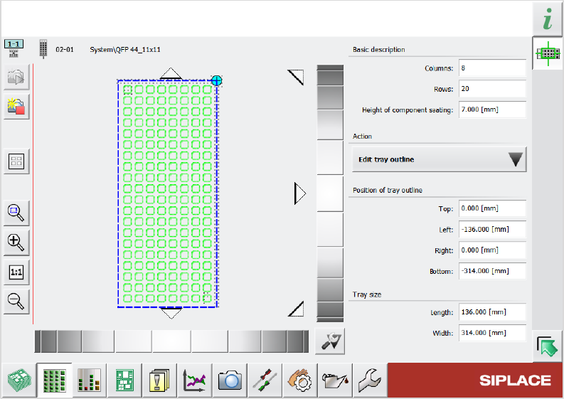
Previously, when editing a tray description, there were two dialogs available to do so: A “simplified”
dialog and an “advanced” dialog. These two dialogs have now been merged into one single dialog.
This new dialog has the same layout as the previous simplified dialog with additional functions from
the advanced dialog. The picklist in the Selected pocket group from the simplified dialog has been
renamed Action and now contains an Edit tray outline option. With this option, you can determine
the position of the tray using the schematic graphic on the left and edit the numerical values of the
position and the size of the tray.
Figure 15-2: New dialog for editing tray description
15.7 Component Camera (Type 48) 8x8 GigE and PCB Camera
(Type 54) Supported
Compatible mode: Hidden
The following new camera types are supported:
– Component Camera (Type 48) 8x8 GigE for E by SIPLACE placement machines
– PCB Camera (Type 54)