SIPLACE Station Software 7xx to 714 介绍.pdf - 第29页
Station Software 7xx to 714.0 (R20-2) / Feature Description 11/2020 Edition 29 4.13 New PCB conveyor system A new PCB conveyor system has b een introduced for the S X1/SX2 placement machine. The most important features o…
Station Software 7xx to 714.0 (R20-2) / Feature Description 11/2020 Edition
28
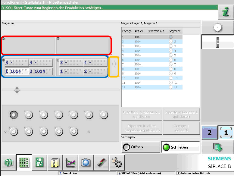
The figure above displays that four magazine carrier locations are mechanically available for this
machine configuration. Magazine carriers are installed on the magazine carrier locations 1 and 2
(blue border). The magazine carrier locations 3 and 4 (red border) are empty. The orange border
displays the nozzle reject bin.
The station software checks if the magazines are correctly installed and are valid for the installed
placement head. Otherwise, the corresponding magazine is displayed on the GUI.
4.11.2 Reject Bins
The disposal of components is a firm part of the placement cycle. Different reject bins are available,
depending on component range, placement head and machine type. For each reject procedure the
suitable bin is found and accessed.
Always the smallest possible bin for the component is selected and only as a last possibility, the
nozzle reject bin is used. If several bins or the component reject channel are considered, the travel
distance is minimized.
For each gantry on the SX1/SX2 placement machine there are five positions for component reject
bins and nozzle reject bins, four positions for the components and one position for the nozzles.
Maximal four reject bins can be installed at the same time (three for components and one for
nozzles). The station software checks if the reject bins are available and correctly installed.
Otherwise, the missing/incorrectly installed reject bin is diplayed on the GUI.
4.12 Gripper for TwinHead
The station software supports the gripper (non-standard nozzle) for TwinHead on the SX1/SX2
placement machine.
Station Software 7xx to 714.0 (R20-2) / Feature Description 11/2020 Edition
29
4.13 New PCB conveyor system
A new PCB conveyor system has been introduced for the SX1/SX2 placement machine. The most
important features of the conveyor system are listed in this section.
4.13.1 Transport Modes
The station software supports the single conveyor and dual conveyor modes on the SX1/SX2
placement machine. The "Quad Lane" conveyor mode is not supported.
4.13.2 Fixed Rail Position in Single Conveyor Mode
In single conveyor mode the rail is fixed with screws on the SX1/SX2 placement machine. The rail
can be adjusted to three additional positions. For this, the operator first has to set the desired
position on the GUI (SIPLACE Service activity level, under Conveyor Configurations – Fixed rail
options) and then unscrew the screws manually.
In dual conveyor mode the rail can be automatically adjusted in the same way as on the X-series.
4.13.3 Calibration Data for Conveyor Control
After booting, the conveyor type of the conveyor system is checked. If the corresponding ID differs
in conveyor system and station software an error message is displayed. The operator is prompted
to calibrate the conveyor manually and to restore the calibration data of the conveyor. If the ID was
"0" in the conveyor system, a generated ID is transferred to the conveyor system together with the
calibrated and restored machine data.
The ID cannot be entered manually.
4.13.4 Thick Board Option
Boards with a thickness up to 6.5 mm can be transported and clamped with this option. After an
appropriate hardware rebuild, the option can be set under SIPLACE Service – Conveyor
Configurations on the station software GUI and gets stored in the conveyor system.
4.13.5 Heavy Board Option
The conveyor system can handle heavy boards on the SX1/SX2 placement machine. In single
conveyor mode boards up to 5 kg and in dual conveyor mode boards up to 2 kg can be
transported.
The heavy board mode has to be set in den PCB Options in Siplace Pro and is transmitted to the
conveyor system. The option is displayed as a small weight icon between input conveyor and
processing conveyor in the Production view.
If the conveyor system detects a heavy board and the heavy board mode was not set, an error
message is displayed at the station. If the operator has inserted a heavy board manually, he or she
will be prompted to remove it.

Station Software 7xx to 714.0 (R20-2) / Feature Description 11/2020 Edition
30
4.13.6 Rotational Angle Compensation for Short, Wide Boards
In this station software the PCB position (offset and angle) per PCB type and the stopper position
are taught if mechanical stoppers are available. The station software uses the detected position of
the current board to determine the start position of the following board.
Restrictions
After the station software has been shut down, the start offset is not available anymore.
4.13.7 Display of Conveyor Input/Output States on the GUI
As the conveyor hardware does not have any LEDs to display the input/output states, all conveyor
inputs/outputs are displayed on the GUI, so that the operator can check them. Additionally, the
operator can set single outputs, if the placement machine is not in placement mode. The SIPLACE
Service activity level is required for this feature.
4.13.8 Boards on Sensor in Input Conveyor
It is not possible to put the boards manually on the sensor in the input conveyor on the SX1/SX2
placement machine. However, the board has to be put manually on the conveyors (but not on the
sensor). By pressing the Drive board button in the Production view, the board in the input
conveyor is transported onto the sensor.
4.14 Changeover Tables 60 and 30
The station software supports the changeover table 60 and the changeover table 30 on the
SX1/SX2 placement machine. The changeover table 60 accomodates a table with 60 tracks. The
changeover table 30 accomodates a table with 30 tracks.
4.14.1 New Location Type WPC + Changeover Table 30
A WPC (Waffle Pack Changer) and a changeover table 30 can be placed side by side at one
location of an SX1/SX2 placement machine. However, the table can only be placed on the right
side of the WPC. The devices get sub-numbers, counted from left to right, beginning with 1.
Although the WPC is not placed, the table gets the sub-number 2.
4.14.2 New Button on the GUI for Inserting/Removing Table
In the Feeders, components and nozzles view, the table can be removed or inserted via a new
button. This allows the access to the conveyor, e.g. to eliminate a PCB jam.
NOTICE
The button is only visible if no docking unit control is available.