SIPLACE Station Software 7xx to 714 介绍.pdf - 第42页
Station Software 7xx to 714.0 (R20-2) / Feature Description 11/2020 Edition 42 5.15 Component Counter – Redundant Storage On the SX-series placement machines there is no hardwa re component counter, but the cou nter stat…

Station Software 7xx to 714.0 (R20-2) / Feature Description 11/2020 Edition
41
5.13.1 Flexible Section Model in the Conveyor Interface
In order to support a variable number of sections, a flexible section model has been added to the
conveyor interface. The section model supports up to 6 sections and the corresponding board
messages and data, like e.g. stop positions.
SX1/2: 3 sections (Input section, Placement section, Output section)
X4/X4i: 5 sections (Input section, Placement section 1, Intermediate section 1, Placement
section 2, Output section)
SX4: 6 sections (Input section, Placement section 1, Intermediate section 1, Intermediate
section 2, Placement section 2, Output section)
5.13.2 Stop Positions for Fixed Conveyor Rail – Conveyor Configurations
All permitted conveyor configurations for the X-series and SX-series placement machines are listed
in the following table:
Frame
Fixed conveyor rail in mm from the center of the machine
191
230
231
234,2
254
256
268
270
281
341
customized
X,
single
-
X
-
-
X
-
X
-
-
-
X
X, dual
-
-
-
X
X
-
X
-
-
-
X
X,
Quad
Lane
-
-
-
-
-
-
X
-
-
-
X
SX1/2,
single
X
-
X
-
-
X
-
-
X
-
-
SX1/2,
dual
-
-
-
X
X
-
X
-
X
-
X
SX4,
dual
-
-
-
-
-
-
X
-
X
X
X
SX4,
Quad
Lane
-
-
-
-
-
-
-
X
X
X
X
Table 5-1: Stop positions for fixed conveyor rail - conveyor configurations
5.14 LDU_X Module – Multiple Squeegee Cycles, Warnings
Dependent on the consistency of the flux media a single squeegee cycle might not be sufficent to
initially apply the flux media evenly. Therefore, it is possible to activate multiple squeegee cycles at
once in the following cases:
– the safety circuit of the machine gets closed (e.g. after the cover was opened)
– the operator activates a squeegee cycle via the GUI
In all other cases a single squeegee cycle will be performed.
The number of the squeegee cycles can be changed on the GUI as of the "Machine Service"
activity level. Default value is 1. After removing the LDU or rebooting the machine, the default value
is valid again.
Additionally, warnings are displayed on the GUI, for example referring to a low filling level.
Station Software 7xx to 714.0 (R20-2) / Feature Description 11/2020 Edition
42
5.15 Component Counter – Redundant Storage
On the SX-series placement machines there is no hardware component counter, but the counter
status is stored in the EEPROM of the IO unit. If the IO unit is exchanged the counter status goes
along with it. Therefore, as of this station software the counter states are stored redundantly in the
IO unit and in an individual file on the station computer and are additionally marked with the device
ID of the GCU in order to be robust against the exchange of single sub-systems.
The counter status persists in the following cases:
– The IO unit is exchanged but the GCU and the station computer are not exchanged.
– The station computer is exchanged but the GCU and the IO unit are not exchanged.
– The GCU is exchanged.
Restrictions
If more than one of the three components GCU, I/O unit and station computer are exchanged, a
correct counter status cannot be ensured after the exchange.
5.16 Enhanced Endurance Run Functionality for Test Purposes
During the endurance run all axes and the MTC/WPC are referenced and a nozzle scan is
performed if there are nozzles on the placement head. Additionally, the tape cutter and the
conveyor can be activated. For this a board must have been inserted. When the endurance run is
started, the number of repeats can be entered on the GUI under Manual operations – Endurance
Tests – Machine endurance runs. The Machine service activity level is required to perform the
endurance runs. The single endurance runs are not synchronized, only the reference run and the
tape cutter are executed sequentially.
5.17 Improved Z-Teaching during Pick-Up – Detection of Empty
Divisions
If components are to be picked up with nozzles that have not been vacuum validated and no
component sensor is available (e.g. as for Twin Head), during the Vision measurement this station
software version can detect, whether the component has been picked up or the pick-up movement
went into an empty pocket/empty division. Teaching of the Z-pick-up height is not performed until
the Vision measurement was successful. Thus, a false teaching of the Z-pick-up height can be
prevented and axis errors and machine stops avoided.
5.18 Detection of Component Missing at Nozzle
If components are to be placed with nozzles that have not been vacuum validated and no
component sensor is available (e.g. as for Twin Head), as of this station software version it can
additionally be detected whether a component has not been placed via a statistical evaluation of
the actual Z-positions of a placement position. The component height must be at least 5 mm and
the Z-placement positions of the board must be robustly taught. Further, the nozzle has to be
length validated. In this case the placement position is marked for inspection and the Z-placement
position will not be taught.
Station Software 7xx to 714.0 (R20-2) / Feature Description 11/2020 Edition
43
5.19 Setting Build Time on the GUI
There are several times describing the duration of the production process:
Cycle-Time: is a production line property that exposes the mean time in which a line accomplishes
boards.
Build-Time: Build time is the time it takes to assemble a specified board in a specified processing
area, including the first fiducial measurement, nozzle exchange and the last placement action.
In the "Statistics – Board performance" view the triggers for start time (first fiducial
measurement) and end time (last placement action) of the build time can be set via a button.
5.20 Enhanced SIPLACE Vision Functionality
The Vision system can now also recognize tape pockets in black blister tapes during the feeder
position recognition without having to teach the tape pockets before.
Until now, only tape pockets in white paper tapes could be recognized with the default settings.
Features (V704.02: Compatible Mode V703.03)
5.21 Settings for Manual Tray Carrier SX
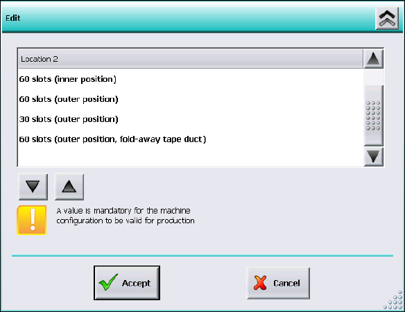
If the manual tray Carrier SX is used, the insert frame with the fold-away tape guide channel is
required. For this, the operator has to make manual settings in the Auto-configuration under
Machine configuration on the Machine service activity level.
Figure 5-3: Settings for manual tray Carrier SX
The 60 slots (outer position, fold-away tape duct) entry has to be set for the table location.
Thus, the 27x27 reject bin and the left reject channel on the location are excluded from the
configuration.