SIPLACE Station Software 7xx to 714 介绍.pdf - 第48页
Station Software 7xx to 714.0 (R20-2) / Feature Description 11/2020 Edition 48 6.6 LED Placement 6.6.1 Changeover Support for LED Feeders The station software provi des a function for placement machines with LED feeders …
Station Software 7xx to 714.0 (R20-2) / Feature Description 11/2020 Edition
47
6.4 Support of Long Boards on SX4
On the conveyor type for the SX4 placement machine, boards up to 450 mm length x 560 mm
width are supported. The boards are positioned backwards in the placement section. I.e., a board
is transported into the placement section until the rearmost board edge resides in the placement
section. After that, the stopper is run up in the input section and the board in the placement section
is positioned backwards at the stopper.
6.4.1 Additional Stopper for 380 mm Long Boards
A new stopper is supported for 380 mm long boards. Thus the configuration contains three
stoppers (Standard, Backwards and Stop380). The station accepts at most two stopper positions at
the same time. In a SIPLACE Pro job, either the Backwards or the Stop380 positioning can be
used.
6.5 Alternative Components
Manufacturer-specifically, components of the same type may lightly differ from each other (e.g. in
the geometry, different tape sizes etc.). This means, that the delivered components also differ from
the definition in the placement program. As of this stations software version the placement of such
components is supported. All valid alternative components are defined in SIPLACE Pro. The
selection, which alternative components are to be placed, has to be defined via the forced setup
verification and thus, Setup Center is required for his function. The alternative components to be
placed are displayed on the station software GUI under Feeders, components and nozzles –
Setup – X-feeders / WPC / MTC as follows:
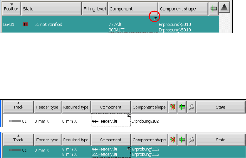
Figure 6-1: Alternative components on WPC (no component selected yet)
The alternative components are marked with a double arrow icon in the upper right corner of the
component name field. By clicking in this field, all possible alternative components are displayed for
the selected pick-up position. In order to select an alternative component for the pick-up position,
the operator has to verify one of the displayed alternatives.
The selected alternative component is displayed in compact display mode and sorted first in
expanded mode:
Figure 6-2: Alternative components at an X-table (444FeederAlti selected)
This function requires a license via SIPLACE Pro. More information on alternative components can
be found in the User Manual for alternative components, item no. [00196839-xx].
Restrictions
The placement of alternative components is only possible in combination with SIPLACE Setup
Center.
Station Software 7xx to 714.0 (R20-2) / Feature Description 11/2020 Edition
48
6.6 LED Placement
6.6.1 Changeover Support for LED Feeders
The station software provides a function for placement machines with LED feeders with which
these feeders can be emptied for a changeover. Before a changeover, all feeders must be emptied
to get filled with components of another illumination class combination. On the Advanced
Production activity level the operator can start the Empty feeder function in the Feeders,
components and nozzles – Setup view via the Feeder details. The function must be activated for
each single feeder. For the components that are picked up/rejected with this function, there is an
additional reject bin placed on the component table.
6.6.2 LED Machine Configuration
As the LED feeders used today are delivered with component tables of their own, some hardware
parts are not needed in combination with the LED feeders. Therefore, a new cost-saving machine
configuration is offered: the X4 configuration X4-LED. This machine is equipped with a DX-table
with FCU/2 but tape cutter and unlocking rail are failing.
6.7 Teaching of Placement Positions during Placement
For some components there is a mismatch between the component shape description and the
placement position on the board. Without adaptations on the board, the component would be
placed on the wrong position in such cases. The station software provides a new function with
which the user is able to adapt the placement positions on the board with aid of the PCB camera.
Example:
Especially for plugs with connections for through-plating on a board (centering pins or springs) it is
more important to fit the contact pins exactly into the through holes as to put the described leads on
the solder pads during placement.
Via SIPLACE Pro or in the Placement positions view on the station, placement positions can be
marked as "to teach". In the placement positions list they are then marked accordingly.
During placement the procedure stops straightly before the component is set and it is then possible
for the user to manipulate the placement position. The user can correct the placement position or
intentionally ignore the teaching request. The placement continues in both cases.
If the placement position is corrected the user can additionally decide, if the component is to
appear in a schematic shape or real on the photo of the PCB camera.
Considering the component dimension and the placement angle now one or more live photos are
made of the placement position by the PCB camera that are put together to an overall picture and
displayed on the GUI. On the basis of this view the placement position can be moved and/or
rotated.
The corrected placement position can be stored. The correction does not only affect the currently
taught placement positions, but also analog positions on identical copies of the part panel. Hereby,
the new placement position is transmitted to SIPLACE Pro. The product does not have to be
specified again.
All changes of the placement positions get noticed by the station software and are entered in the
local event log.

Station Software 7xx to 714.0 (R20-2) / Feature Description 11/2020 Edition
49
NOTICE
The placement positions can only be corrected, if the user has the corresponding access
rights in SIPLACE Pro to modify a position on a panel. To release the correction
possibility, the user first has to authenticate himself or herself.
Restrictions
– Viewing the whole line, it is not possible to teach all placement positions of a board on a single
placement machine. Only the placement positions that in fact are placed on a station are listed
for selection. I.e., in order to correct all placement positions, the board has to be moved
through the whole line.
– No integrity check is performed at the station after the teaching action. As the station restores
to SIPLACE Pro and a download subsequently takes place to the other placement machines,
an integrity check is performed by SIPLACE Pro. This might fail, if it is impossible to go to the
resulting placement positions.
6.8 Brightness Calibration of Digital Camera Systems
Brightness calibration (calculation and comparison of the individual illumination brightness) of the
digital sensor systems for the cameras is intended to ensure that the same component with an
identical component shape description can be measured on all machines. In order to achieve this,
the brightness value must correspond across all the sensor systems. Initial calibration is carried out
ex works. However, since experience shows that sensor systems become dirty and darker with the
time, calibrating them again on-site at the customer improves recognition of components,
particularly on older machines.
As of this station software version, brightness calibration can also be performed simply on-site at
the customer. To allow this, the GUI has been extended to include the function Calibrate
illumination. This makes it possible to carry out automatic brightness calibration for every
component camera or PCB camera configured on the placement machine.
Requirements:
– The machine has to be empty.
– The FCCS tool “Camera calibration plate FCCS digital“, on which the special calibration tools
for calibrating the illumination of all digital cameras currently in use are located. You can get
more information about this tool through the SIPLACE Service.
– The operator has logged in on the Machine service or SIPLACE service activity level.