SIPLACE Station Software 7xx to 714 介绍.pdf - 第55页
Station Software 7xx to 714.0 (R20-2) / Feature Description 11/2020 Edition 55 6.17 Settings for Manual Tray Carrier SX If the manual tray Carrier SX is used, the insert frame with the f old-away tape guide channel is re…

Station Software 7xx to 714.0 (R20-2) / Feature Description 11/2020 Edition
54
6.14 SIPLACE Random Setup Feature for Trays
The station software offers the SIPLACE Random Setup feature for a flexible setup of tray feeders.
The most important feature is the random setup for trays. For this, the trays have to be marked as
random in SIPLACE Pro and the system has to be run together with SIPLACE Setup Center.
The following use cases are possible:
– A tray that is described in the target setup can be set up on another level. Thereby, another
random target specification may be suppressed. Target setup means the setup that is specified
in SIPLACE Pro and is sent to the station.
– A tray that is described in the target setup can be set up several times, i.e. additional trays may
be added.
The feature can be used for WPC5, WPC6 und MTC.
At the station random feeders / trays are marked with a double arrow ( ) in the Feeders,
components and nozzles view.
Restrictions
The feature only works in combination with SIPLACE Setup Center.
6.15 Pneumatic Stopper for SX-Series
As of this station software version all SX-series conveyors are equipped with pneumatic stoppers
instead of the former standard mechanical stoppers. The conveyors recognize different
configurations and so they can be operated with different stopper configurations.
6.16 Zero Point Calibration for Twin /DP Axes
Until now the zero correction for Twin / dp axes was determined with the aid of a special calibration
nozzle.
As of this station software version the empty nozzle interface of the segment (i.e. without nozzle) is
measured via SIPLACE Vision for calibration instead. The operator only has to remove the existing
nozzle from the segment before. Additionally, the calibration is not performed segment-wise but
head-wise.
Station Software 7xx to 714.0 (R20-2) / Feature Description 11/2020 Edition
55
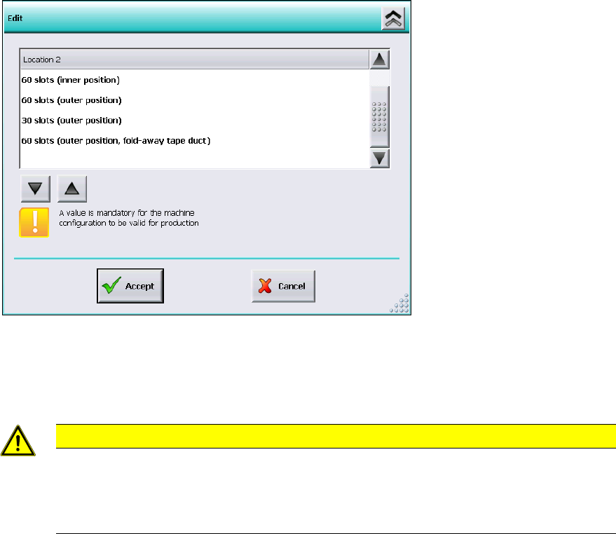
6.17 Settings for Manual Tray Carrier SX
If the manual tray Carrier SX is used, the insert frame with the fold-away tape guide channel is
required. For this, the operator has to make manual settings in the Auto-configuration under
Machine configuration on the Machine service activity level.
Figure 6-5: Settings for manual tray Carrier SX
The 60 slots (outer position, fold-away tape duct) entry has to be set for the table location.
Thus, the 27x27 reject bin and the left reject channel on the location are excluded from the
configuration.
CAUTION
If this setting is not made the component may be rejected over the tray and the Z-axis
may dash hard against the tray.
On upgrading from station software versions <=704 the settings in the Auto-configuration
have to be checked accordingly, if the manual tray Carrier SX is used.
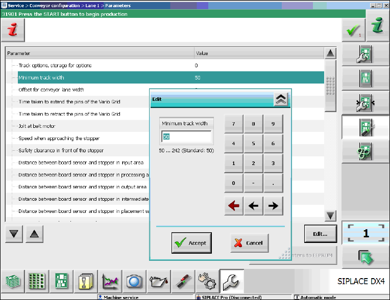
6.18 Adjustable Minimum Track Width
Special mechanical factors of the conveyor (e.g. wider mechanical stoppers in customized
solutions) may cause restrictions for the conveyor width. The serial minimum conveyor track width
cannot be adjusted anymore. To prevent this, the minimum conveyor track width can be adjusted
for the SX-series and DX-series placement machines. Under Conveyor configuration the
operator can adjust the new Minimum track width parameter on the Machine service activity
level as follows.
Station Software 7xx to 714.0 (R20-2) / Feature Description 11/2020 Edition
56
Figure 6-6: Adjusting the minimum track width
► Select the Minimum track width parameter.
► Click Edit.
► Set the desired rack width with the numeric pad in the edit window.
► Click Accept to save the setting.