SIPLACE Station Software 7xx to 714 介绍.pdf - 第56页
Station Software 7xx to 714.0 (R20-2) / Feature Description 11/2020 Edition 56 Figure 6-6 : Adjusting the minimum track width ► Select the Minimum track wi dth parameter. ► Click Edit . ► Set the desired rack width with …
Station Software 7xx to 714.0 (R20-2) / Feature Description 11/2020 Edition
55
6.17 Settings for Manual Tray Carrier SX
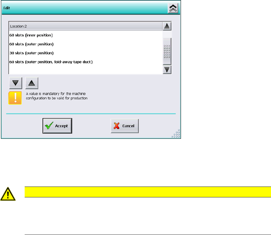
If the manual tray Carrier SX is used, the insert frame with the fold-away tape guide channel is
required. For this, the operator has to make manual settings in the Auto-configuration under
Machine configuration on the Machine service activity level.
Figure 6-5: Settings for manual tray Carrier SX
The 60 slots (outer position, fold-away tape duct) entry has to be set for the table location.
Thus, the 27x27 reject bin and the left reject channel on the location are excluded from the
configuration.
CAUTION
If this setting is not made the component may be rejected over the tray and the Z-axis
may dash hard against the tray.
On upgrading from station software versions <=704 the settings in the Auto-configuration
have to be checked accordingly, if the manual tray Carrier SX is used.
6.18 Adjustable Minimum Track Width
Special mechanical factors of the conveyor (e.g. wider mechanical stoppers in customized
solutions) may cause restrictions for the conveyor width. The serial minimum conveyor track width
cannot be adjusted anymore. To prevent this, the minimum conveyor track width can be adjusted
for the SX-series and DX-series placement machines. Under Conveyor configuration the
operator can adjust the new Minimum track width parameter on the Machine service activity
level as follows.
Station Software 7xx to 714.0 (R20-2) / Feature Description 11/2020 Edition
56
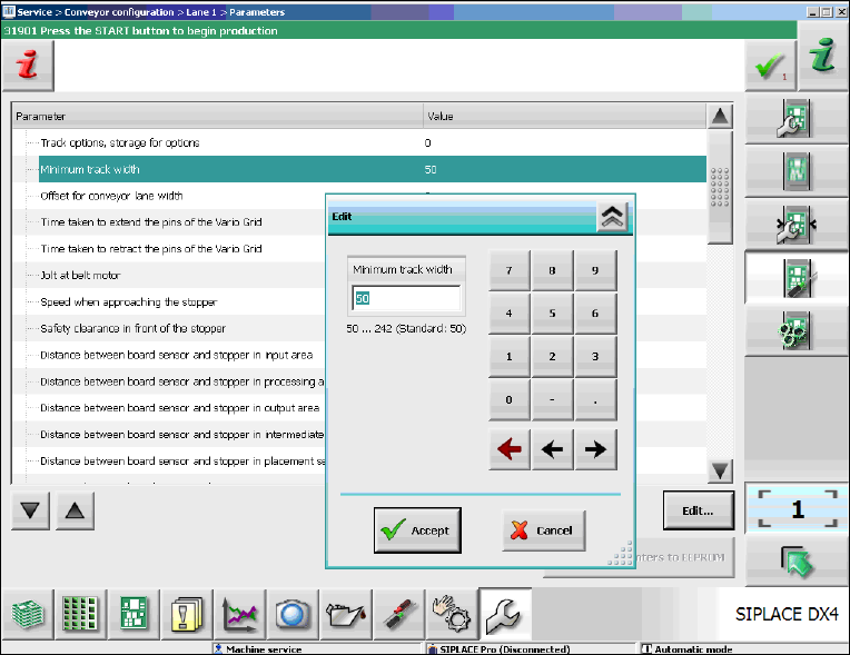
Figure 6-6: Adjusting the minimum track width
► Select the Minimum track width parameter.
► Click Edit.
► Set the desired rack width with the numeric pad in the edit window.
► Click Accept to save the setting.
Station Software 7xx to 714.0 (R20-2) / Feature Description 11/2020 Edition
57
6.19 Setting Lamp Indicator (Two-Colored or Three-Colored)
The towers of the X-, SX- and DX-series placement machines are equipped with two lamp
indicators (one on each side of the machine). Until now these lamp indicators were two-colored
(green / white) on the X- and SX-series placement machines. With the aid of the different states of
the single lamp indicators (including the flashing frequency) the operator can recognize the
machine status (i.e. production, waiting state, error type etc.). Additionally, a three-colored lamp
indicator (green / yellow / red) is supported as of this station software version:
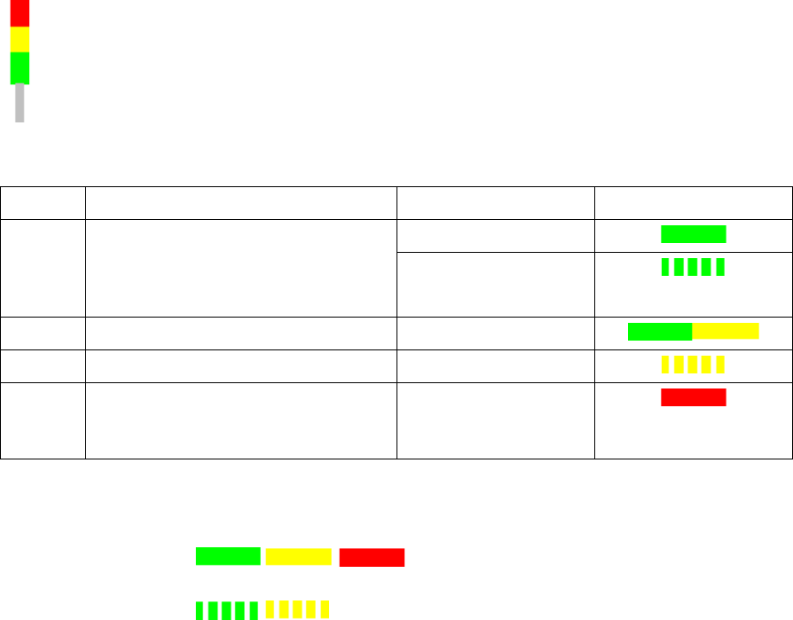
The three-colored lamp indicator is explicated in the following table.
Level
Action
Machine state
Lamp indicator
1
none
Production
– Manual operation
– Idle production
2
Attention required
Production
3
Immediate reaction
Break / Stopped
4
Immediate reaction
(technical assistance might be
required)
Down
Table 6-1: Three-colored lamp indicator
Key
Constantly
illuminated:
Flashing:
The relative lamp indicator (two-colored or three-colored) must be set in the Auto-configuration, see
the installation manual to the station software, item no. [00196771-xx].
6.20 Two-Row Nozzle Changer on SX1/SX2 for C&P20A and CPP
The two-row nozzle changer is supported for the C&P20A and CPP placement heads on the
SX1/SX2-series placement machines.
6.21 Extended Range for Customized Nozzles for CPP and Twin Head
The range for customized nozzles has been extended as follows:
– Twin Head: 5500-5999 (5xx) nozzles
– CPP head: 2500-2799 (20xx) and 2900-2999 (28xx)