SIPLACE Station Software 7xx to 714 介绍.pdf - 第74页
Station Software 7xx to 714.0 (R20-2) / Feature Description 11/2020 Edition 74 The following behavior has been implemented in the station soft ware to increase the pickup robustness: 1. For 2x8mm feeders a syst em fiduci…
Station Software 7xx to 714.0 (R20-2) / Feature Description 11/2020 Edition
73
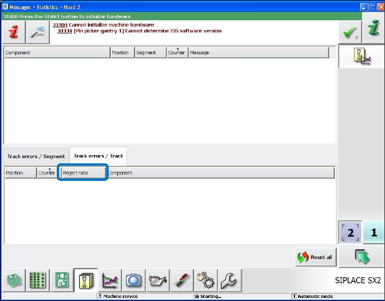
7.13 Reject Ratio in % Per Track
In order to facilitate a specific troubleshooting when feeder errors occur, the reject ratio in % per
track is displayed in the new Reject ratio column in the Messages – Statistics – Head – Track
errors / Track view as of this station software version.
Figure 7-9: Reject ratio in % per track
7.14 Robust Pocket Recognition for Big Components
Up to now, it was not possible to perform robust pocket recognition for components bigger than the
0402 model due to the non-uniform pocket models and different tape types (paper, black blister
and transparent blister). Pocket recognition errors often occurred for big components what caused
frequent machine stops.
As of this station software version, pocket recognition errors for big components do not cause
machine stops. The pickup process is started without displaying any error message on the GUI. If
successful, components can be picked up and optimized by teaching the X- and Y-pickup positions
anyway. Otherwise a track error occurs.
Station Software 7xx to 714.0 (R20-2) / Feature Description 11/2020 Edition
74
The following behavior has been implemented in the station software to increase the pickup
robustness:
1. For 2x8mm feeders a system fiducial is measured on the feeder.
2. If the fiducial cannot be measured, this does not cause any machine stop and no warning is
displayed on the GUI of the station software.
3. For components <= 0402 an additional tape pocket measurement is performed as before.
During this subsequent tape pocket measurement the position to go to is already corrected by
the correction value of the system fiducial.
4. If the tape pocket measurement with customer-specifically taught tape pockets fails, this will not
cause any machine stop and no error measurement will be displayed in the main view on the
GUI of the station software.
The failing measurement will only be displayed in the detailed view of the error list.
5. The behavior for system tape pockets remains unchanged. The machine stops when a
measurement fails.
7.15 Automatic Pocket Recognition with Height Calibration
Up to now, the automatic pocket recognition with height calibration was only triggered by Vision
errors.
As of this station software version, tape pockets and pickup height are also measured again if a
pickup error occurs on a feeder track (after n pickup trials).
7.16 Automatic Finishing of MTC Refill Position
As already realized for the WPC, the refill position is automatically finished for the MTC as well as
of this station software version.
The refill position is finished as soon as the door and the interlock of the MTC are locked.
7.17 Improved Error Classification in the Statistics View
The error classification in the Statistics view on the GUI of the station software has been
improved. The following error types are displayed:
– Pickup errors: Component not on nozzle after pickup
– Vision errors: Component recognition via Vision failed
– Process errors: contain the following errors without any further differentiation
Component not present before placement
Component present after placement
Component present before pickup
Station Software 7xx to 714.0 (R20-2) / Feature Description 11/2020 Edition
75
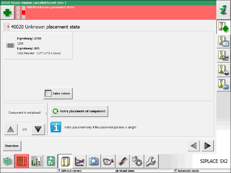
7.18 Automated Workflow after "Unknown placement status"
The Unknown placement status occurs when the placement machine recognizes or assumes
that components have been dipped in the solder paste or swept away. Up to now, the operator had
to act himself and navigate to a dialog box to create an image of the placement position and take
one of the following decisions:
– Repair is possible.
– Component has been successfully placed.
– Processing of the board must be canceled.
As of this station software version, a (multiple) image is automatically created of the placement
position. The inverse and abstract component shape is shown over the placement position. A
detailed error message is displayed and in this view the operator can take one of the above-
mentioned decisions (please refer to the following figures).
Figure 7-10: Unknown placement state – Repair possible