SIPLACE Station Software 7xx to 714 介绍.pdf - 第96页
Station Software 7xx to 714.0 (R20-2) / Feature Description 11/2020 Edition 96 7.31 New TrayStak Feeder AX Feeder Type Compatible mode: Not supporte d As of this station software version, the new TrayStak Feeder AX feede…

Station Software 7xx to 714.0 (R20-2) / Feature Description 11/2020 Edition
95
Light barriers are installed as stoppers for the board at fixed positions in the conveyor system: one
light barrier for each conveyor segment (input belt, processing areas, intermediate belt, output
belt). When the Long Board option is used, no additional light barrier is installed, but the offset is
configured/modified only. The board is then moved forward until it lies with the rear edge at the
stop position defined by the offset.
There is no mechanical stopper.
7.30 Placement of Tall Components with Very High Force Pick&Place
Head and WPC5 / WPC6
Compatible mode: Not supported
As of this station software version, components up to a height of 30mm can be placed with a force
of 70 N. The WPC5 can transport such components as of serial number 1485, the WPC6 as of
serial number C1486.
NOTICE
WPC6 – Tall Components as of Level 4 Only!
Due to the refill module, components > 25 mm cannot be positioned on the levels 1 – 3
and 27 – 28 on the WPC6. The levels 4 – 28 will be set up automatically by the SIPLACE
Pro Optimizer. The levels 1 – 3 must be blocked manually by the operator.
For this purpose, the new Very High Force Pick&Place Head (named VHF P&P head in the
following) has been developed. The VHF P&P head is derived from the existing Twin Head but has
one segment only.
The VHF P&P head is supported on the SX1/SX2 V2 placement machine. In addition, a PCB
camera is needed that is installed at another, higher position.
The VHF P&P head and the camera model (SST 34 H) are automatically detected in the Auto
Configuration.
For placement with the mentioned maximum values, there is a new short nozzle type: 508. It is
based on nozzle type 518 but is shorter. Nozzle type 508 can also be used by the Twin Head.
Station Software 7xx to 714.0 (R20-2) / Feature Description 11/2020 Edition
96
7.31 New TrayStak Feeder AX Feeder Type
Compatible mode: Not supported
As of this station software version, the new TrayStak Feeder AX feeder type is supported on the
X4i S placement machine for CPP placement heads.
The TrayStak Feeder AX has one level with a waffle pack tray for which the size is defined in the
setup, and a stacked inventory of further waffle pack trays that obeys the FIFO rule. The current
waffle pack tray cannot be exchanged by another tray of the inventory until all components have
been picked up.
The behavior after pick-up errors is as follows:
– If a component is rejected by SIPLACE Vision, the software searches for an empty division in
the current tray. The current tray might not be the same as the original pick-up tray.
– If the current tray is complete, the component is rejected.
– If an empty division is found, the software reserves it to put the component back there later.
– At that time, no more components are picked up to prevent that the current tray with the empty
division(s) gets exchanged.
– Pick-up will not be possible until all components have been successfully put back.
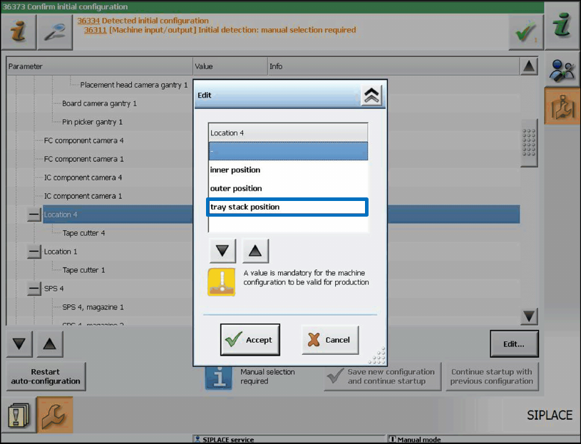
Due to mechanical deviations on the installed feeder, the operator must define manually for each
location in the Auto Configuration when the software is started for the first time, whether there is a
TrayStak Feeder AX on it.
Figure 7-30: TrayStak Feeder AX present
Station Software 7xx to 714.0 (R20-2) / Feature Description 11/2020 Edition
97
WARNING
Changing Filling Level Manually after Exchanging Waffle Pack Tray and Pick-up
Errors!
With the buttons on the feeder a new waffle pack tray can be made available. However,
the filling level is not automatically modified at the station.
If the operator does not change the filling level manually, the pick-up sequence will be
continued at the filling level of the last waffle pack tray and some components will get
lost.
If the filling level is not manually modified after a waffle pack tray has been exchanged
and the components will be put back in the tray according to the configuration, it may
happen that they are put pack at occupied positions. Thus, strange noises arise, and
damages might result.
7.32 FCU State Display on the GUI
Compatible mode: Complete
In combination with a manual table, the LED state display and the DIP switch on the FCU (Feeder
Control Unit) are invisible or inaccessible on the SX1/SX2, DX1/DX2, SX4 and DX4 placement
machines.
For check and test purposes it is therefore possible to display the following states for the locations
1-4 on the GUI for these placement machines.
1. Lock state of the single nozzle changers (open / closed).
2. Magazine checking state for the single nozzle changer magazine location of the different
nozzle changers (magazine present / not present).
3. States of the reject bin query sensors (bin available / not available). The states of the sensors
that are not requested in the current bin configuration are explicitly shown (head / gantry
modularity).
4. Air blast valve output of the nozzle station (air blast enabled / disabled).
5. Current preset state of the FCU DIP switch (enabled / disabled).