Nordson_EFD_RV_Series_Operating_Manual - 第125页
RV Series Automated Dispensing Systems 125 www.nordsonefd.com info@nordsonefd.com +1-401-431-7000 Sales and service of Nordson EFD dispensing systems are available worldwide. Setting Up the Optional Tip Detector or Tip A…
RV Series Automated Dispensing Systems
124 www.nordsonefd.com info@nordsonefd.com +1-401-431-7000 Sales and service of Nordson EFD dispensing systems are available worldwide.
AppendixB, Non-Wizard Setup Procedures
All setup and calibration procedures are guided by the Robot Initial Setup wizard, which should be used after any
system change, including tip change-out. However, the procedures in this appendix can be performed individually
and are provided here for your reference as needed.
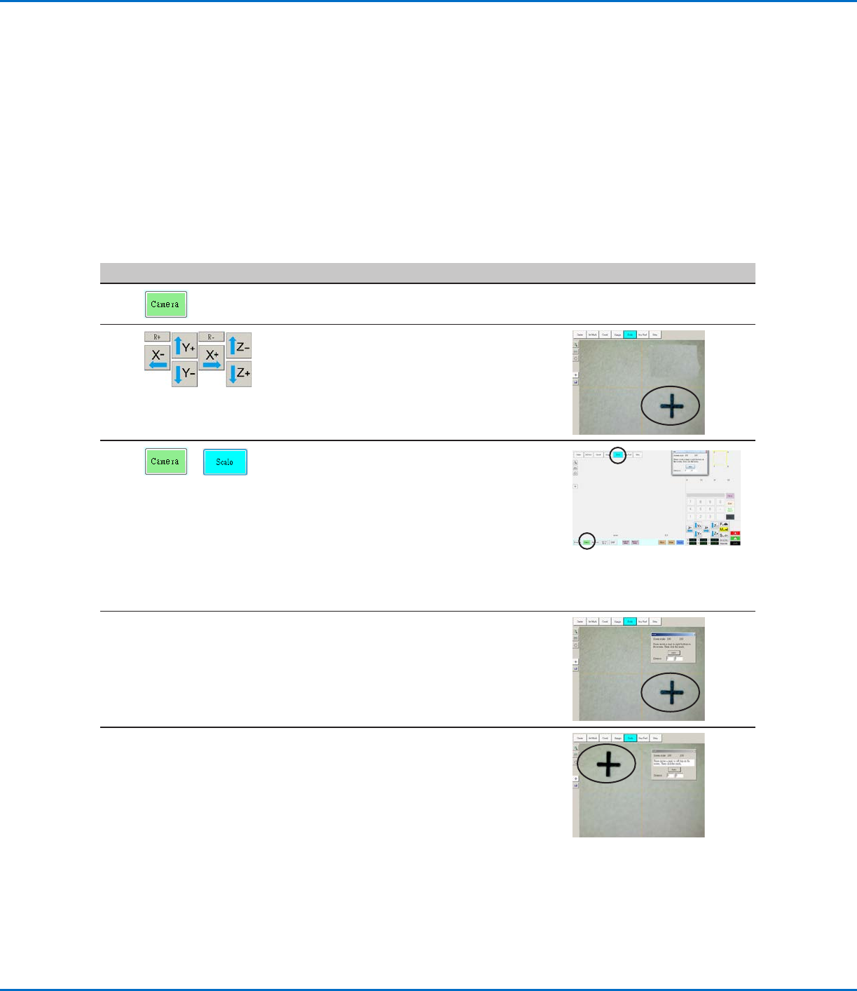
Setting the Camera Scale
PREREQUISITES
The system is fully installed (including the dispensing valve) and includes fluid.
The bottom of the tip is lower than the bottom of the camera.
The workpiece is present on the fixture plate.
# Click Step Reference Image
1
• Click the CAMERA tab.
2
• Jog the camera to a point of reference that
is located on the lower right corner of the
workpiece.
• Bring the image into focus. Refer to
“Camera” on page16 as needed for
instructions on focusing the camera.
3
>
• Click the CAMERA tab and then click
SCALE.
The Scale window opens.
NOTE: When the camera views an object, it
converts the pixels to a true measurement.
For the camera to make this conversion
accurately, you must “teach” the camera
what the size of an object is in comparison
to pixels per inch by setting the camera
scale.
4 • Choose a point of reference on the
workpiece and jog the camera so that the
reference point is located in the lower right
quadrant of the camera screen, then click
the point.
5 • Jog the camera again until the same
reference point is located in the upper left
quadrant of the camera screen, then click
the point.
The camera scale is now set.
RV Series Automated Dispensing Systems
125www.nordsonefd.com info@nordsonefd.com +1-401-431-7000 Sales and service of Nordson EFD dispensing systems are available worldwide.
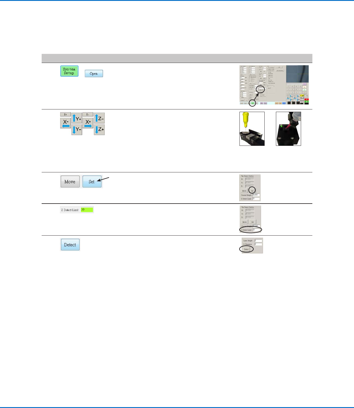
Setting Up the Optional Tip Detector or Tip Alignment Device
#
Click Step Reference Image
1
>
• Click SYSTEM SETUP > OPEN.
2 • Jog the tip until it is positioned about 2mm
above the sensor on the tip detector or the
crosshairs on the tip alignment device.
Sensor on
the optional
tip detector
Crosshairs on
the optional tip
aligner
3 • Under Tip Detect Device, click SET (next to
Move).
• Click YES when prompted for confirmations.
4 • Under Tip Detect Device, enter a value of
10(mm) Z Detect Limit.
5 • Under Tip Detect Device, click DETECT.
• Click YES/OK when prompted for
confirmations.
The robot raises the tip to Z = 0, then lowers
the tip onto the sensor to detect the tip
offset.
AppendixB, Non-Wizard Setup Procedures
(continued)
RV Series Automated Dispensing Systems
126 www.nordsonefd.com info@nordsonefd.com +1-401-431-7000 Sales and service of Nordson EFD dispensing systems are available worldwide.
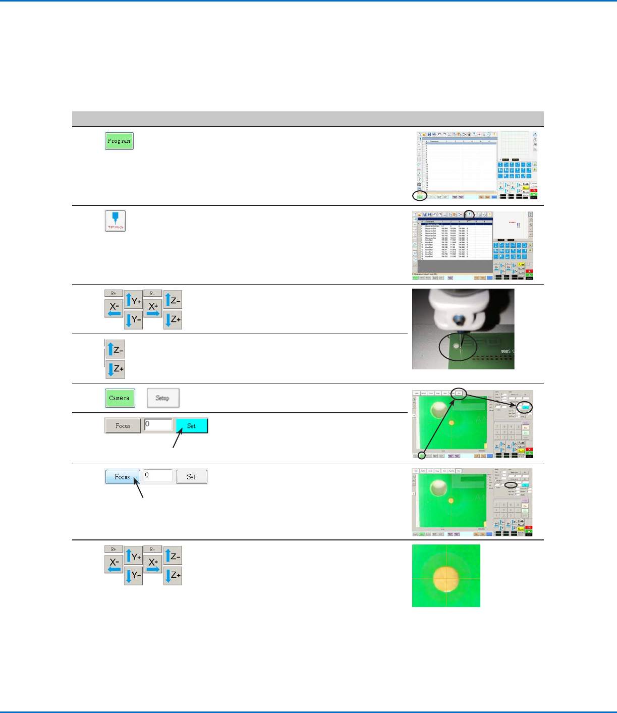
Setting the Tip-to-Workpiece Offset (Z Clearance) Using the Camera
Focus
#
Click Step Reference Image
1
• Click the PROGRAM tab.
2 • Click the CCD Mode icon to change to the
Tip MODE.
3 • Jog the tip to a good reference point on the
workpiece.
4 • Jog the tip down until the desired dispense
gap is reached.
5
>
• Click CAMERA > SETUP to return to the
Offset fields.
6 • Click SET next to Focus.
NOTE: The Set button should be bright
blue.
7
• Click FOCUS next to Set.
8 • Jog the camera until the camera crosshairs
are centered over the dispense dot you
created earlier.
• Focus the camera until the image of the
dispense dot is clear. Refer to “Camera” on
page16 as needed for instructions on
focusing the camera.
AppendixB, Non-Wizard Setup Procedures
(continued)