Nordson_EFD_RV_Series_Operating_Manual - 第141页
RV Series Automated Dispensing Systems 141 www.nordsonefd.com info@nordsonefd.com +1-401-431-7000 Sales and service of Nordson EFD dispensing systems are available worldwide. # Click Step Reference Image 7 2 > • Enter…
RV Series Automated Dispensing Systems
140 www.nordsonefd.com info@nordsonefd.com +1-401-431-7000 Sales and service of Nordson EFD dispensing systems are available worldwide.
AppendixE, Multi-Needle Setup and Use (continued)
To Use the Multi Needle Command in a Program
PREREQUISITES
The system is properly set up. Refer to “Setting Up and Calibrating the System (Required)” on page45.
The additional dispensers are installed and set up and the Multi Needle capability is enabled. Refer to “To Enable
Multi-Needles Dispensing” on page137 and to “To Set the Camera-to-Tip Offsets for Multiple Dispensers” on
page137.
A test workpiece is positioned on the fixture plate or work surface.
NOTE: This procedure explains the programming process for two dispensers. Repeat steps as needed to add
commands for additional dispensers (up to four dispensers can be installed).
# Click Step Reference Image
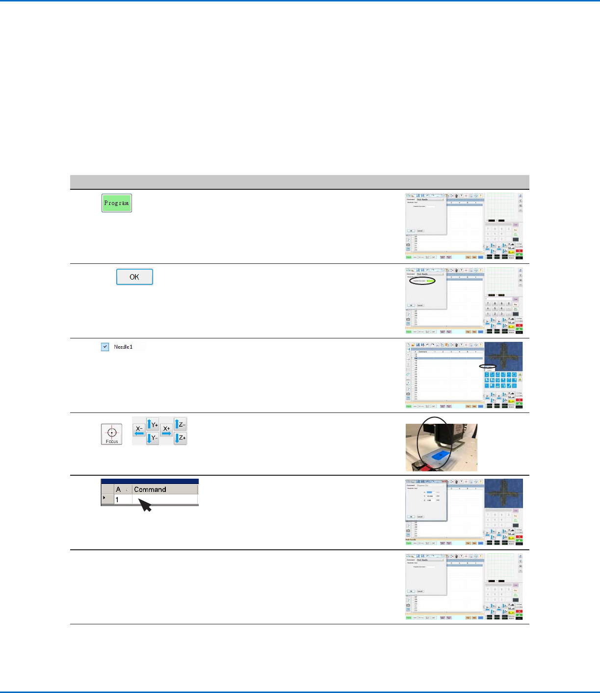
1
> MULTI NEEDLE
• Click the PROGRAM tab
• Double-click the address row where you
want to insert a Multi Needle command and
select MULTI NEEDLE.
2
1 >
• Enter the number of the dispenser to
dispense from at this point in the program
(in this example, Dispenser 1).
• Click OK to save.
3
• In the Secondary View screen, right click and
check the NEEDLE 1 checkbox.
4
>
• Click the FOCUS icon to focus the camera.
• Jog the camera until the camera crosshairs
are centered over the desired target on the
workpiece.
5 • Insert the required commands for
Dispenser1 (for example, create dispense
dots or lines).
6
MULTI NEEDLE
• Double-click the address row where you
want to insert the second Multi Needle
command and select MULTI NEEDLE.
Continued on next page
RV Series Automated Dispensing Systems
141www.nordsonefd.com info@nordsonefd.com +1-401-431-7000 Sales and service of Nordson EFD dispensing systems are available worldwide.
# Click Step Reference Image
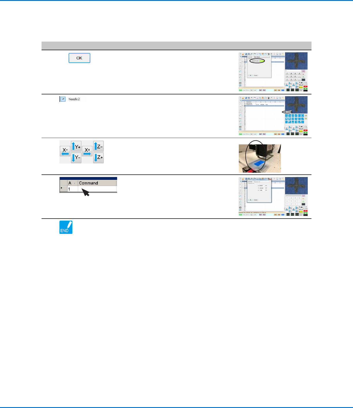
7
2 >
• Enter the number of the dispenser to
dispense from at this point in the program
(in this example, Dispenser 2).
• Click OK to save.
8 • In the Secondary View screen, right click
and check the NEEDLE 2 checkbox.
9 • Click the FOCUS icon to focus the camera.
• Jog the camera until the camera crosshairs
are centered over the desired target on the
workpiece.
10 • Insert the required commands for
Dispenser2 (for example, create arc or fills).
11 • Click END PROGRAM to end the program.
The system will dispense from Dispenser 1
or Dispenser 2 as programmed.
AppendixE, Multi-Needle Setup and Use (continued)
To Use the Multi Needle Command in a Program (continued)
RV Series Automated Dispensing Systems
142 www.nordsonefd.com info@nordsonefd.com +1-401-431-7000 Sales and service of Nordson EFD dispensing systems are available worldwide.
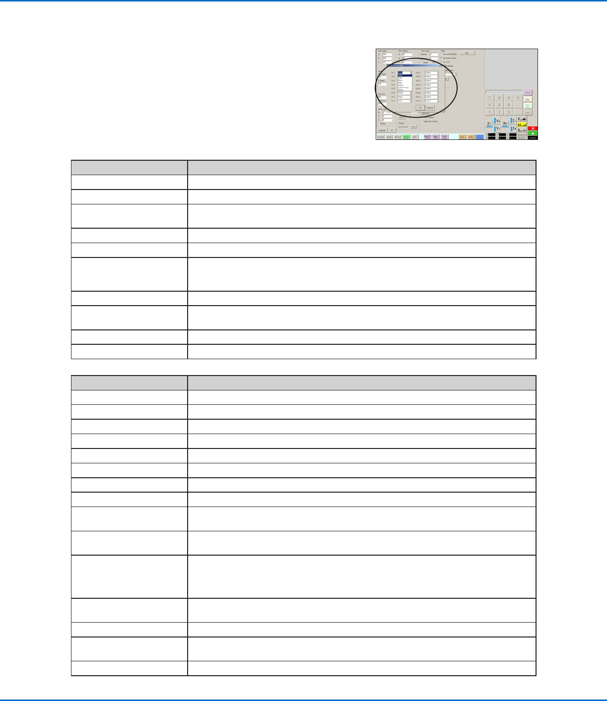
AppendixF, I/O Pin Function Setup
The I/O Pin Function capability, accessed through the Expert menu on the
System Setup screen, provides a set of user-configurable conditions that
can be assigned to the available inputs and outputs on the I/O Port. These
conditions affect the operation of the robot.
IO Pin Function Configurations
Input Configuration Description
Input Default setting.
Start A signal to start the execution of the dispense program.
Door A signal to stop the execution of the dispense program. This configuration is to be used in
tandem with the DOOR OPEN output configuration.
Stop A signal to stop the execution of the dispense program.
Home A signal to home/reinitialize the robot after a stop of the dispense program.
Table Ready A signal to indicate that the system is ready to execute the dispense program. The dispense
program will not execute if the input signal is off. This configuration is to be used in tandem
with the TABLE READY output configuration.
Pause A signal to pause the execution of the dispense program.
Call Program A signal to initiate a different program. Use the Call Program selection from the Expert menu to
specify the program to call.
XY Adjust A signal to initiate Needle XY Adjust.
Z Detect A signal to initiate Needle Z Detect.
Output Configuration Description
Output Default setting.
Emergency A signal indicating that the robot has stopped.
EMG-B A signal indicating that the Emergency Stop button on the robot is pressed.
Running A signal indicating that the dispense program is currently executing.
Homing A signal indicating that the robot is reinitializing/moving to home position.
Standby A signal indicating that the robot is in a standby (idle) position.
Pause A signal indicating that the dispense program is paused.
System Start A signal indicating that the DispenseMotion software is open and running.
Table Ready A signal indicating that the system is ready to execute the dispense program. This configuration
is to be used in tandem with the TABLE READY input configuration.
Door Open A signal indicating that the door is open. This configuration is to be used in tandem with the
DOOR input setting.
No Start Trigger A signal indicating that the program cannot run until the TABLE READY input signal is ON.
When the TABLE READY input is ON, the NO START TRIGGER indication switches OFF.
This configuration must be used with the TABLE READY input and the TABLE READY output
configurations.
Teach Mode A signal indicating that the robot is in the Teach mode. This signal can be used when the
external start / stop box is present.
Calibration Execution A signal indicating that the robot is performing a Needle Z Detect or a Needle XY Adjust.
Positional Error A signal indicating an over-limit warning after a general over-limit warning from program
execution occurs.
In Home A signal indicating that the tip is in the Park Position.