Nordson_EFD_RV_Series_Operating_Manual - 第35页
RV Series Automated Dispensing Systems 35 www.nordsonefd.com info@nordsonefd.com +1-401-431-7000 Sales and service of Nordson EFD dispensing systems are available worldwide. View 2 of the navigation and jogging window Vi…
RV Series Automated Dispensing Systems
34 www.nordsonefd.com info@nordsonefd.com +1-401-431-7000 Sales and service of Nordson EFD dispensing systems are available worldwide.
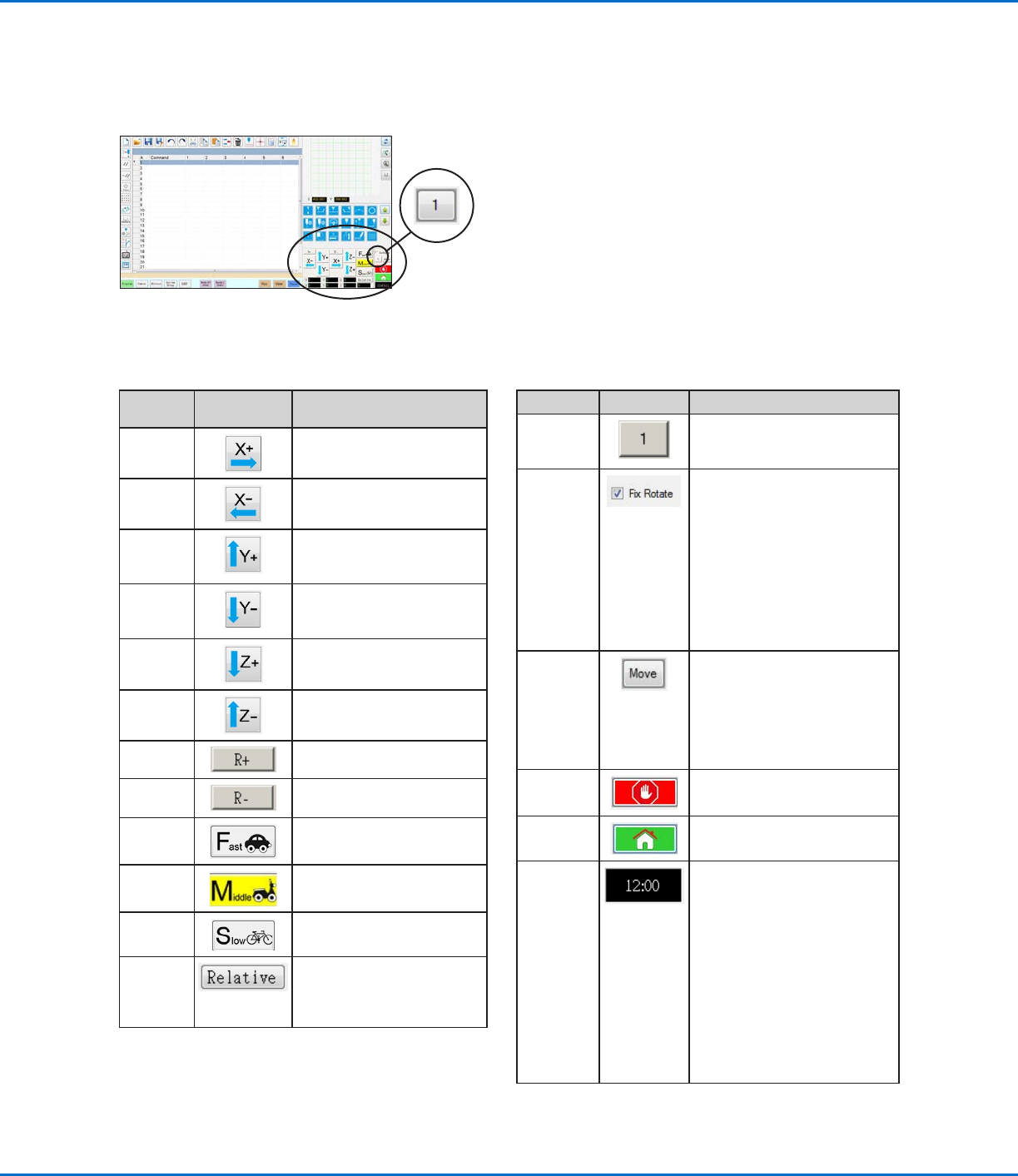
Navigation and Jogging Window
Use the icons on the navigation and jogging window to move the dispensing tip. Click the 1 button to change the
window to an alternate view that allows you to change the jog speed values. These windows also include an actual
time / cycle time display, a dispense actuation counter, and coordinate value displays.
Icon
Name
Icon Function
X+
Jogs the X axis to the right
X- Jogs the X axis to the left
Y+
Jogs the Y axis backward
(moves the fixture plate
forward)
Y-
Jogs the Y axis forward
(moves the fixture plate
backward)
Z+
Jogs the Zaxis down
Z-
Jogs the Zaxis up
R+
Jogs the Raxis clockwise
R-
Jogs the Raxis
counterclockwise
Fast
Fastest jogging speed
Middle Medium jogging speed
Slow Slowest jogging speed
Relative Sets the origin relative to the
coordinates of the workpiece.
Coordinates are displayed
next to the button.
View 1 Both Views
Icon Name Icon Function
Jog button
toggle
Toggles the navigation and
jogging window between view1
and view 2
Fix rotate
Used in tandem with the R+ and
R- buttons.
When checked:
• In CCD Mode, the camera
rotates around a fixed point.
• In Tip Mode, the tip rotates
around a fixed point.
When unchecked, the Raxis
rotates along the Zaxis.
Move
Opens the Move to Position
window, which allows you
to move the tip to specific
coordinates. Refer to “How
to Move the Tip to a Specific
Location” on page35 for
details.
Stop Stops the robot
Home Sends the robot to the home
position (0, 0, 0)
Clock /
stopwatch
(Click the box to toggle the
display) Shows the time for
the time zone selected in the
DispenseMotion controller’s
operating system OR acts as a
stopwatch to time how long a
program runs.
When toggled to the stopwatch,
the time resets to 0:0:0. When
you select Run, the stopwatch
starts counting and then stops
counting when the program
finishes.
View 1 of the navigation and jogging window
RV Series Automated Dispensing Systems
35www.nordsonefd.com info@nordsonefd.com +1-401-431-7000 Sales and service of Nordson EFD dispensing systems are available worldwide.
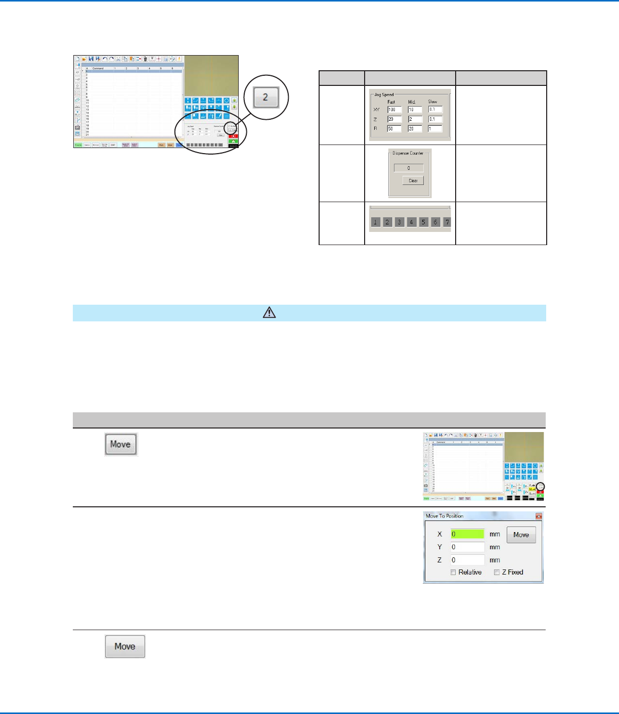
View 2 of the navigation and jogging window
View 2
Field Screen Area Function
Jog
Speed
Allows you to change
the jog speed settings
by entering values
using the keyboard.
Dispense
Counter
Shows how many
dispense actuations
have occurred. Click
CLEAR to reset the
counter to zero (0).
Input /
output
triggers
Allows you to trigger
a connected input /
output by clicking the
input / output number.
Navigation and Jogging Window (continued)
CAUTION
Risk of equipment damage. When moving the tip to a specific location, do not exceed the axis limits (specified
under System Setup > Axis Limits), especially for the Z axis. Doing so can damage the robot or cause the tip to
collide with the substrate.
How to Move the Tip to a Specific Location
You can use the Move button in the jog window to move the tip to a specific set of coordinates.
#
Click Step Reference Image
1
• In the jog window, click MOVE.
The Move to Position window opens.
2 • Enter the desired coordinates. As applicable,
select or deselect the following checkboxes:
- Relative: If selected, the tip will move to the
entered coordinates relative to its current
location. If deselected, the tip will move
to the entered coordinates based on the
home position (0, 0, 0).
- Z Fixed: When selected, locks out the Z
axis so only X and Y coordinates can be
entered.
3 • Click MOVE.
The tip moves to the specified location.
• Close the window.
RV Series Automated Dispensing Systems
36 www.nordsonefd.com info@nordsonefd.com +1-401-431-7000 Sales and service of Nordson EFD dispensing systems are available worldwide.
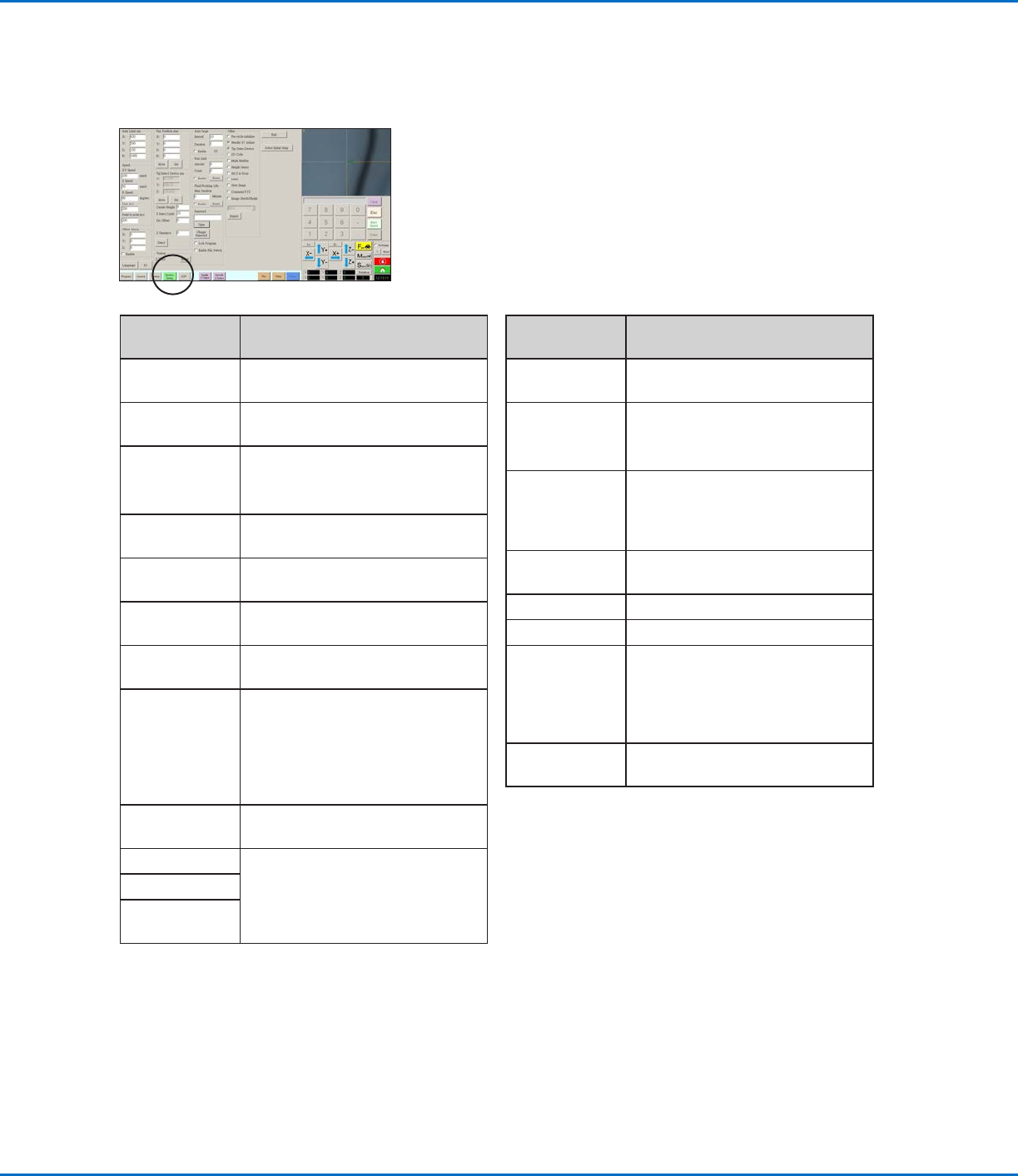
System Setup Screen
Click the System Setup tab to go to the System Setup screen. This screen includes fields for system settings and
provides access to the Robot Initial Setup wizard. Refer to the sections of the manual referenced below for detailed
information on these fields.
System Setup
Screen Area
Function
Axis Limit Refer to “Setting System
Parameters” on page41.
Speed Refer to “Setting System
Parameters” on page41.
Line Acc
Point to point
Acc
Refer to “Setting System
Parameters” on page41.
Offset Alarm Refer to “Setting System
Parameters” on page41.
Language Refer to “Setting System
Parameters” on page41.
IO Refer to “Setting Up Inputs /
Outputs” on page58.
Park Position Refer to “Setting System
Parameters” on page41.
Tip Detect
Device
Used only as needed for manual
calibration of the tip-to-workpiece
offset in place of using the Robot
Initial Setup wizard. Refer to
“AppendixB, Non-Wizard Setup
Procedures” on page124.
Version Shows the current version of the
software
Auto Purge Refer to “How to Set Up Auto
Purge, Program Cycle Limits,
or Fluid Working Life Limits” on
page84.
Run Limit
Fluid Working
Life
System Setup
Screen Area
Function
Password Refer to “Setting Password
Protection” on page44.
Lock Program
Enable File
Switch
Refer to “How to Lock or Unlock a
Program” on page67.
Other Allows you to enable or disable a
variety of system-level settings.
Refer to “Other” on page43 for
details.
Model drop-
down menu
Specifies the robot model.
Expert For advanced users only.
Exit Closes the software.
Robot Initial
Setup
Opens the system setup and
calibration wizard. Refer to
“Setting Up and Calibrating the
System (Required)” on page45
for the system setup procedures.
Light (if
present)
Refer to “Setting System
Parameters” on page41.