Nordson_EFD_RV_Series_Operating_Manual - 第49页
RV Series Automated Dispensing Systems 49 www.nordsonefd.com info@nordsonefd.com +1-401-431-7000 Sales and service of Nordson EFD dispensing systems are available worldwide. Example of the how the green arrow changes bas…
RV Series Automated Dispensing Systems
48 www.nordsonefd.com info@nordsonefd.com +1-401-431-7000 Sales and service of Nordson EFD dispensing systems are available worldwide.
Setting Up the System Using the Robot Initial Setup Wizard
The Robot Initial Setup wizard guides you through all the steps required to properly set up the system, including the
calibration and setting of offsets.
Important: The tip will not rotate, either virtually or physically, until the tool centering calibration portion
(Step1) of the Robot Initial Setup wizard has been performed.
Opening the Robot Initial Setup Wizard and Setting the Angle of Rotation
# Click Step Reference Image
1
>
• Click SYSTEM SETUP > OPEN.
2 • Click ROBOT INITIAL SETUP.
The Robot Initial Setup wizard opens.
NOTE: If the optional tip detector or tip
aligner was installed, the wizard shows an
image of the applicable device.
• Perform the actions on tabs 1–6 one at a
time. The actions are also provided in this
manual for your reference as needed.
NOTE: The wizard buttons change to the
color blue when clicked. All the wizard tabs
include the following two buttons:
- RESET THE 4 AXIS: Click to restart the
wizard from Step 1, using the default
values.
- RESET COLOR: Click to return all
selections on the tab to their default
settings.
Robot Initial Setup wizard
showing the optional tip detector
Robot Initial Setup wizard
showing the optional tip aligner
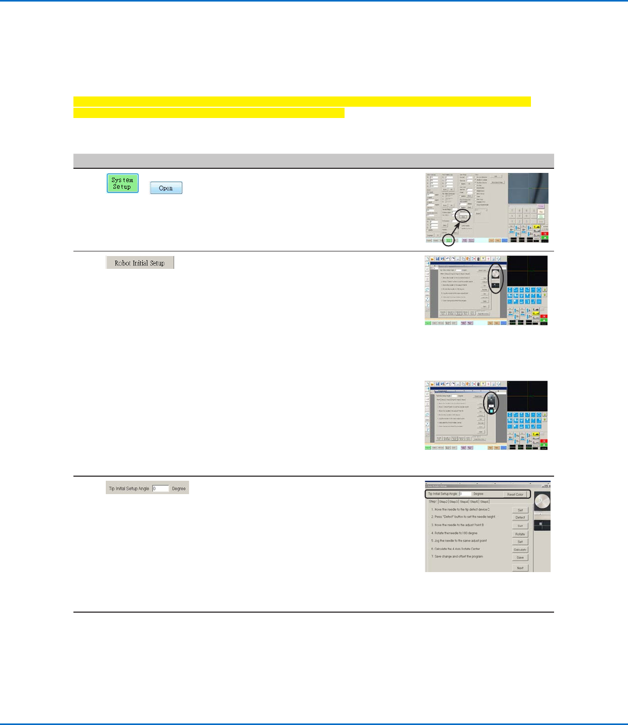
3 • Enter the desired number of degrees for the
Tip Initial Setup Angle.
The green arrow on the screen changes
based on the entered value. Refer to
“Example of the how the green arrow
changes based on the value entered for
Tip Initial Setup Angle” on page49 for
images.
NOTE: Ensure that the angle does not
cause the dispensing device to obscure the
camera view.
4 • Continue to “Robot Initial Setup (Step1
Tab): Setting Up Tip Detection and Tool
Centering Calibration” on page49.
Setting Up and Calibrating the System (Required) (continued)
RV Series Automated Dispensing Systems
49www.nordsonefd.com info@nordsonefd.com +1-401-431-7000 Sales and service of Nordson EFD dispensing systems are available worldwide.
Example of the how the green arrow changes based on the value entered for Tip Initial Setup Angle
Setting Up the System Using the Robot Initial Setup Wizard (continued)
Opening the Robot Initial Setup Wizard and Setting the Angle of Rotation (continued)
Robot Initial Setup (Step1 Tab): Setting Up Tip Detection and Tool Centering Calibration
Important: The tip will not rotate, either virtually or physically, until the tool centering calibration is done.
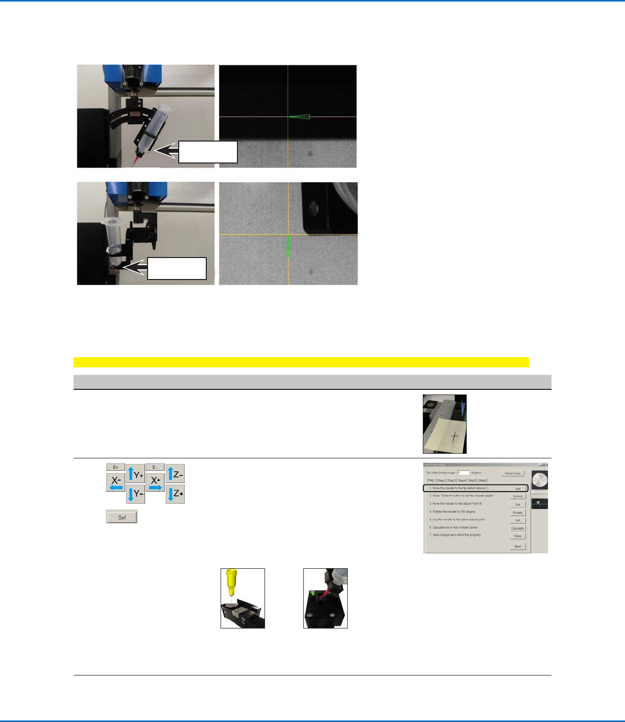
# Click Step Reference Image
1
• If your system does not include the optional
tip detector/aligner, create a crosshair target
and skip to step 4 on page 50.
Crosshair target
created with a
removable note
2
>
• If your system includes the tip detector/
aligner, jog the tip until it is positioned about
2mm above the following, as applicable for
your system (see below for examples):
- The sensor on the optional tip detector
- The crosshairs on the optional tip aligner
• Click SET next to step 1.
Sensor on the
optional tip
detector
Crosshairs on
the optional tip
aligner
NOTE: If your system does not
include the tip detector/aligner,
steps 1–2 are disabled.
Continued on next page
Tip Initial Setup
Angle = 0°
0°
270°
Tip Initial Setup
Angle = 270°

RV Series Automated Dispensing Systems
50 www.nordsonefd.com info@nordsonefd.com +1-401-431-7000 Sales and service of Nordson EFD dispensing systems are available worldwide.
# Click Step Reference Image
3
• Click DETECT.
The system performs the tip detection or
alignment operation.
4
>
• Jog the tip until it is positioned about 2 mm
above the following, as applicable for your
system (see below for examples):
- The crosshair target you created
- The sensor on the optional tip detector
- The crosshairs on the optional tip
alignment kit
NOTE: If present, an image of the optional
tip detector or tip aligner is shown.
• Click SET next to step 3.
5 • Click ROTATE next to step 3.
The tip rotates 180°.
6
>
• Jog the tip to the same calibration point
used in step 3.
• Click SET.
Continued on next page
Setting Up the System Using the Robot Initial Setup Wizard (continued)
Robot Initial Setup (Step1 Tab): Setting Up Tip Detection and Tool Centering Calibration
(continued)