Nordson_EFD_RV_Series_Operating_Manual - 第62页
RV Series Automated Dispensing Systems 62 www.nordsonefd.com info@nordsonefd.com +1-401-431-7000 Sales and service of Nordson EFD dispensing systems are available worldwide. Pr ogramming This section provides how-to proc…
RV Series Automated Dispensing Systems
61www.nordsonefd.com info@nordsonefd.com +1-401-431-7000 Sales and service of Nordson EFD dispensing systems are available worldwide.
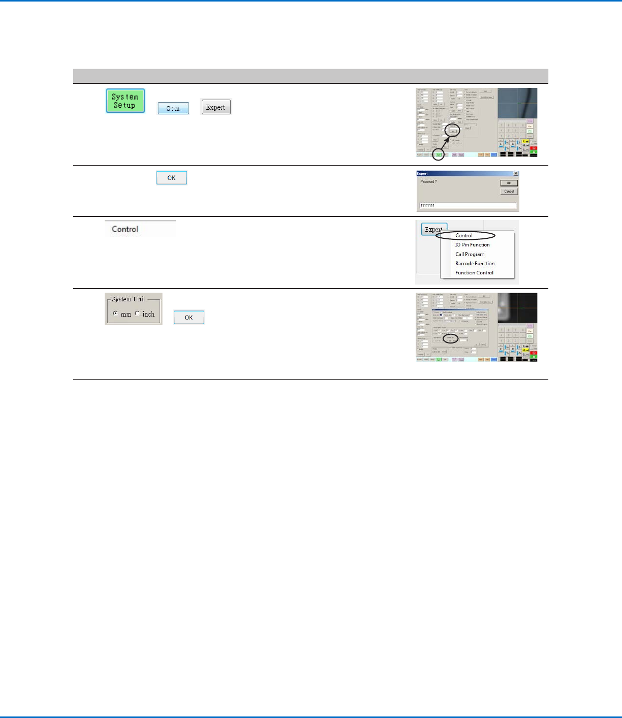
Setting the Units of Measure
By default, the system displays units of measure using the metric system. Follow this procedure to change how the
system displays units of measure.
# Click Step Reference Image
1
> >
• Click SYSTEM SETUP > OPEN >
EXPERT.
2
11111111 >
• Enter 11111111, then click OK.
3 • Click CONTROL.
4
>
• In the Expert window, select the
desired unit of measure under System
Unit.
• Click OK to save the setting.
The system automatically exits the
software to allow the change to take
effect.
Restoring the System to the Factory Default Settings
To restore all settings to their factory default values, open and then close the following file located on the D:\ drive:
D:\ever_sr\Initial Setup.
RV Series Automated Dispensing Systems
62 www.nordsonefd.com info@nordsonefd.com +1-401-431-7000 Sales and service of Nordson EFD dispensing systems are available worldwide.
Programming
This section provides how-to procedures for the most commonly performed programming tasks. Refer to “How
to Create and Run a Program” on page65 for an example of how to use the dispensing software to create
a complete program. If you have difficulty creating a program for your application, contact your Nordson EFD
representative. Before using this section:
• Complete all applicable installation tasks. Refer to “Installation” on page17.
• Complete all required setup tasks. Refer to “Setup” on page41.
• Refer to “Concepts” on page22 for important robot programming concepts and for an overview of the
dispensing software screens and icons.
How to Rotate the Tip and Set the Angle of Rotation
To set the angle of tip rotation, you must first rotate the tip to the desired position, then open the command window
into which the value should be entered. You cannot directly enter the angle of tip rotation in a command window.
Follow these procedures to rotate the tip and to set the angle of rotation for a command window.
IMPORTANT:
• The tip will not rotate, either virtually or physically, until the tool centering calibration portion of the Robot Initial
Setup wizard has been performed. This calculation is Step 1 of the wizard.
• To physically rotate the dispense valve installed on the robot Zaxis head, the system must be in the Tip mode.
The dispense valve will not physically rotate if the system is in the CCD mode.
• You cannot set the rotation angle of the tip inside a command window. To enter the tip rotation angle in a
command window, you must first rotate the tip to the desired position, then open a command window. The
system automatically populates the R field with the current angle of rotation.
Failure to set the angle of tip rotation as described in this section will compromise the integrity of the dispense
pattern. Set the desired angle of tip rotation before opening a command window.
CAUTION
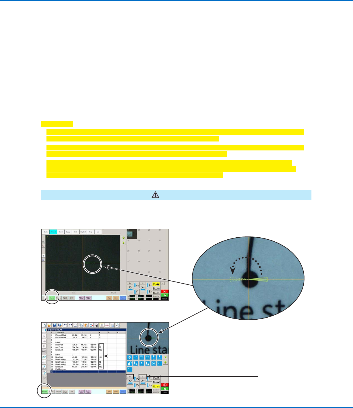
DispenseMotion Screen Elements Used to Show Tip Rotation
The green arrow on the
camera screens shows the
angle of tip rotation.
Camera tab selected
Program tab selected
0°-180°
Column 4 of the dispense
program shows the angle of
tip rotation in degrees.
Use the R+ and R-
keys to rotate the tip
RV Series Automated Dispensing Systems
63www.nordsonefd.com info@nordsonefd.com +1-401-431-7000 Sales and service of Nordson EFD dispensing systems are available worldwide.
How to Rotate the Tip and Set the Angle of Rotation (continued)
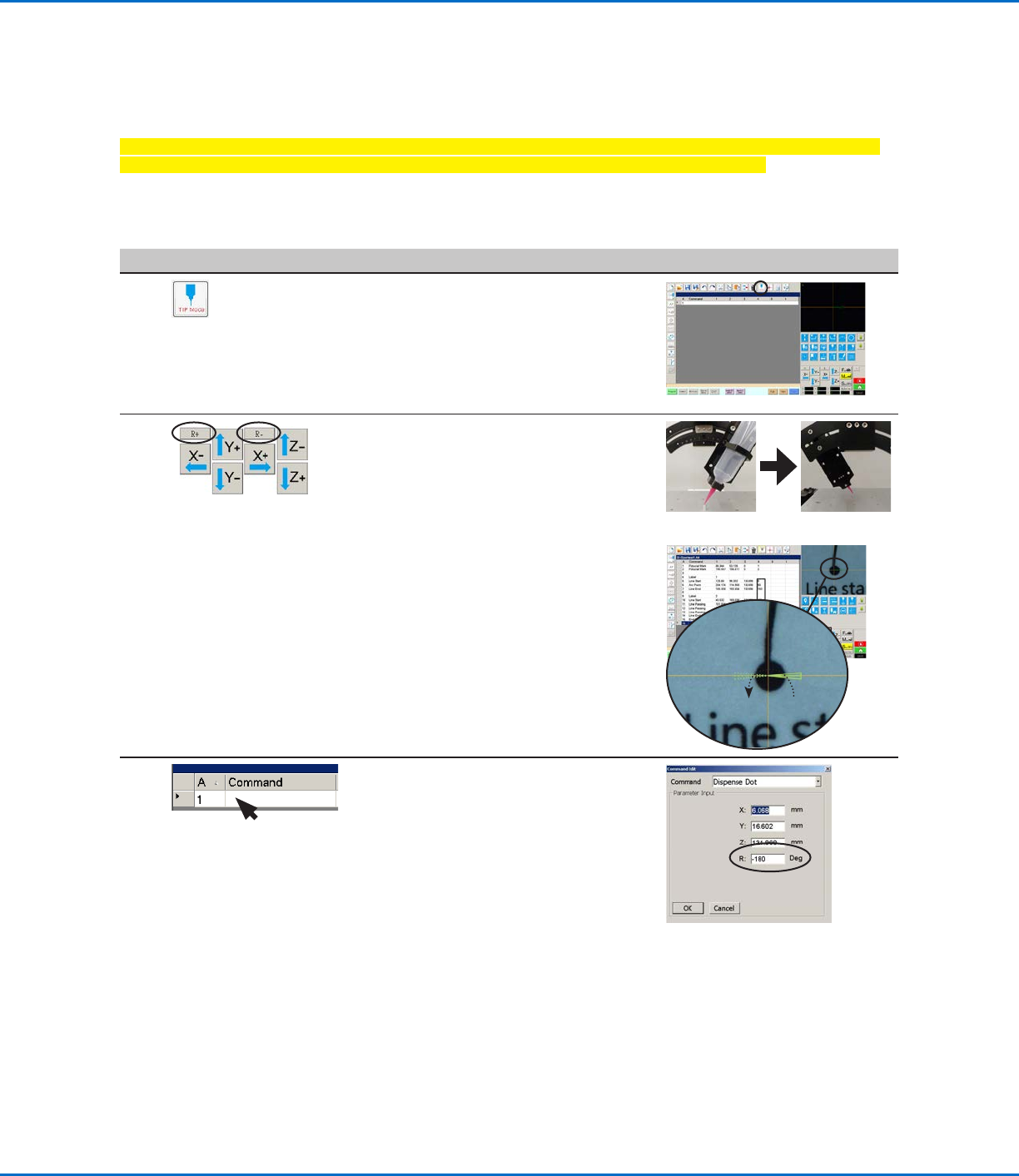
Setting the Tip Rotation Angle in the Tip Mode
Follow this procedure to physically rotate the tip to the desired angle of rotation.
Important: The tip will not rotate, either virtually or physically, until the tool centering calibration portion of
the Robot Initial Setup wizard has been performed. This calculation is Step 1 of the wizard.
PREREQUISITES
The system is properly set up. Refer to “Setting Up and Calibrating the System (Required)” on page45.
# Click Step Reference Image
1
• Click the MODE icon to place the system
in the Tip mode.
NOTE: When the system is in the Tip
mode, the dispense valve and tip installed
on the Zaxis head will rotate; the green
arrow on the camera view screen will also
rotate.
2 • Click R+ to rotate the tip clockwise.
• Click R- to rotate the tip
counterclockwise.
Observe the dispense valve on the robot
Zaxis head to see the rotation, or
observe the green arrow in the Secondary
View screen to see the tip rotation.
0°-180°
3 • Double-click a command address line to
open the command edit drop-down menu
and then open the desired command.
The system automatically populates the
Rfield with the current angle of rotation.
In addition, the values in column 4 of the
command address lines show the tip
rotation angle. Refer to “DispenseMotion
Screen Elements Used to Show Tip
Rotation” on page62 for an illustration.