Nordson_EFD_RV_Series_Operating_Manual - 第96页
RV Series Automated Dispensing Systems 96 www.nordsonefd.com info@nordsonefd.com +1-401-431-7000 Sales and service of Nordson EFD dispensing systems are available worldwide. I/O Port NOTES: • Outputs are rated at 125 mA.…
RV Series Automated Dispensing Systems
95www.nordsonefd.com info@nordsonefd.com +1-401-431-7000 Sales and service of Nordson EFD dispensing systems are available worldwide.
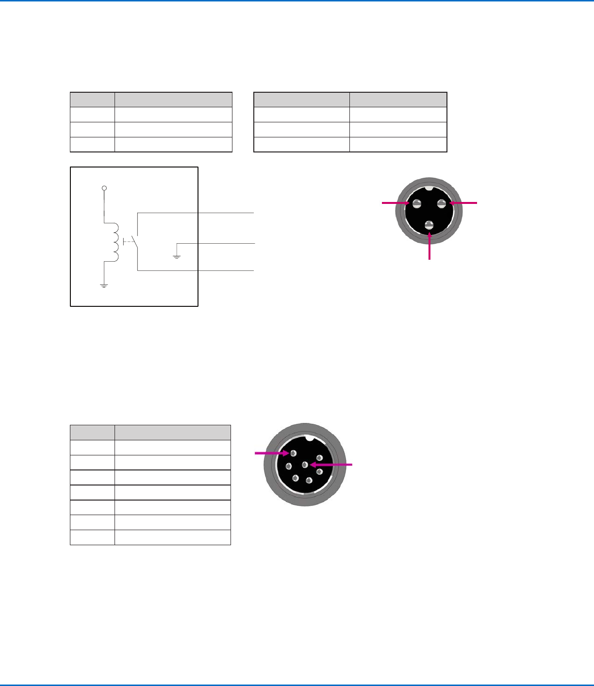
Maximum Voltage Maximum Current
125 VAC 15A
250 VAC 10A
28 VDC 8A
Pin# Description
1 NOM (Normally open)
2 COM (Common)
3 EARTH (Ground)
2
1 3
Pin 1
Pin 2
Pin 3
+24V
Relay
Ext. Control Port
NOTES:
• Inputs are not polarity-sensitive.
• The optional start / stop box accessory facilitates input / output connections to this port. Refer to “Start / Stop
Box” on page92 for part numbers.
Pin Description
1 Ground
2 Start signal
3 Motor power
4 Motion idle
5 Run / Teach
6 Emergency stop
7 Emergency stop
1
7
Technical Data (continued)
Wiring Diagrams
Dispenser Port

RV Series Automated Dispensing Systems
96 www.nordsonefd.com info@nordsonefd.com +1-401-431-7000 Sales and service of Nordson EFD dispensing systems are available worldwide.
I/O Port
NOTES:
• Outputs are rated at 125 mA.
• Courtesy +24 VDC output is rated at 3.0 Amp.
Pin Description Pin Description Pin Description
1 Input 1 10 Not connected 19 Output 6
2 Input 2 11 GND 20 Output 7
3 Input 3 12 GND 21 Output 8
4 Input 4 13 GND 22 Not connected
5 Input 5 14 Output 1 23 Not connected
6 Input 6 15 Output 2 24 +24 VDC
7 Input 7 16 Output 3 25 +24 VDC
8 Input 8 17 Output 4
9 Not connected 18 Output 5
Input schematic Output schematic
Pin 25
Input X
+24V
Output X
Pin 13
+24V
Technical Data (continued)
RV Series Automated Dispensing Systems
97www.nordsonefd.com info@nordsonefd.com +1-401-431-7000 Sales and service of Nordson EFD dispensing systems are available worldwide.
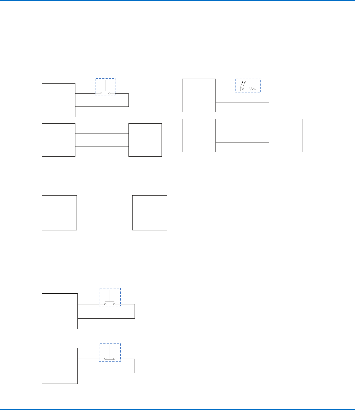
Example Input / Output Connections
You can use the I/O Port and Ext. Control port on the back of the robot to connect a variety of inputs and outputs. A
spare connector is also provided with the system. The following schematics show typical examples of input / output
connections to a robot.
Inputs
Pin 25
PLC Output (+24V)
PLC
SW1
Robot
I/O Port
+24VDC
Robot
I/O Port
Pin 2
Input 2
Pin 11
Ground
Pin 1
Input 1
PLC Ground
Outputs
External Device Powered by the Robot
Pin 24
Device
Robot
I/O Port
+24VDC
Pin 11
Ground
Courtesy +24 VDC output is rated at 3.0 Amp.
Start and Emergency Stop (ESTOP) Connections to Ext. Control
Pin 2
ESTOP
Start signal
Ext. Control port
Pin 7
Emergency
stop
Pin 1
Ground
Ext. Control port
SW1
Pin 6
Emergency
stop
Pin 14
+24V In
Device
LED 1
Robot
I/O Port
Output 1
Robot
I/O Port
Pin 15
Output 2
Pin 11
Ground
Pin 11
Ground
Ground
Outputs are rated at 125 mA.
Technical Data (continued)