3 Stage Conveyor.pdf - 第18页
TECH NICAL RE FERE NCE MECHANICAL DETA IL 1.12 High Throughput Conveyor Manual Chapter Issue 2 May 02 Board Clamp s A board clamping arrangement is utilized to secure the board dur ing the print process and t o m inimize…
TECHNICAL REFERENCE
MECHANICAL DETAIL
Chapter Issue 2 May 02 High Throughput Conveyor Manual 1.11
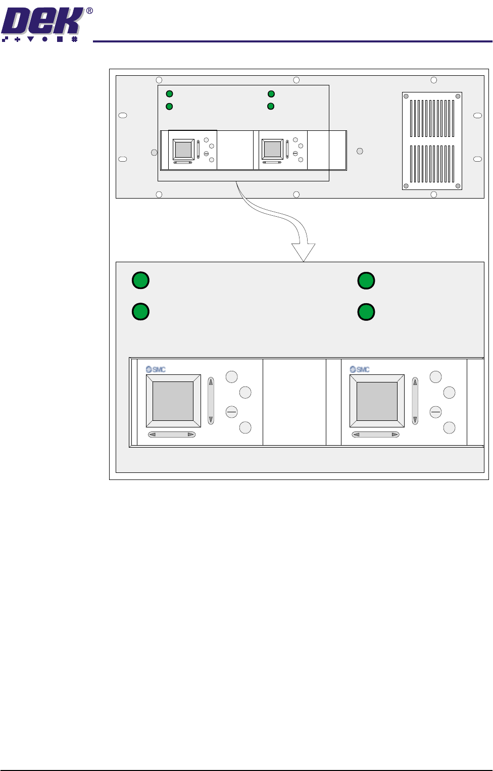
Figure 1-8 3-Stage Conveyor Controller (M27)
1/3 STAGE
OPERATION
1/3 STAGE
OPERATION
FAST TRANSFERS
DISABLED
FAST TRANSFERS
DISABLED
R/H CONVEYOR L/H CONVEYOR
+
ESC
OK
+
OK
ESC
1/3 STAGE
OPERATION
1/3 STAGE
OPERATION
FAST TRANSFERS
DISABLED
FAST TRANSFERS
DISABLED
M27 3-STAGE CONVEYOR 160558
LANE A (R/H) LANE A (L/H)
+
OK
ESC
+
OK
ESC
TECHNICAL REFERENCE
MECHANICAL DETAIL
1.12 High Throughput Conveyor Manual Chapter Issue 2 May 02
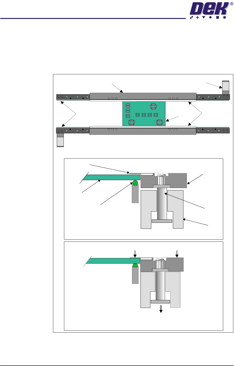
Board Clamps A board clamping arrangement is utilized to secure the board during the print
process and to minimize board distortion. A pneumatically operated piston, (via
a 24V switched solenoid 16SOL10 from the machine controller), lowers the
board clamp and foil, trapping the board on the transport belts. On completion
of the print stroke the board is released by activation of the pneumatic solenoid.
An in-line pneumatic exhaust ensures quick release of the board clamps.
Figure 1-9 Board Clamping Arrangement
Transport Belt
Rail
Piston
Metal Foil
Board Clamp
Board
Pneumatic Piston Driven Downwards
Board Trapped Between Foil and Transport Belt
Board Clamp and Foil Lowered
WARNING SHARP EDGE
PATENT No 5157438
WARNING SHARP EDGE
PATENT No 5157438
Transport Belt MotorBoard Clamp
Transport Belts
Metal Foils
Board
Plan View of Print Station Conveyor
Board Free on Transport Belt
TECHNICAL REFERENCE
MECHANICAL DETAIL
Chapter Issue 2 May 02 High Throughput Conveyor Manual 1.13
Board Snugger
Assembly
The board snugger assembly is an alternative option to the standard board
clamp arrangement. This feature is utilized when there is a requirement to print
close to the board edge.
The adjustable snugger plate, rear rail guide and fixed snugger plates are
interchangeable with similar units to facilitate differences in board thickness.
This system caters for 0.8mm, 1.0mm and 1.6mm board thickness.
To clamp the board in position for the printing process, the board is gripped
between the fixed and adjustable snugger plates by action of the pneumatically
operated piston. Pneumatic operation utilizes the existing board clamp circuit,
(via a 24V switched solenoid 16SOL10 from the machine controller).
On completion of the print stroke the pneumatic solenoid is de-activated allow-
ing the actuator pistons (sprung loaded), to retract the adjustable snugger plate
away from the board.
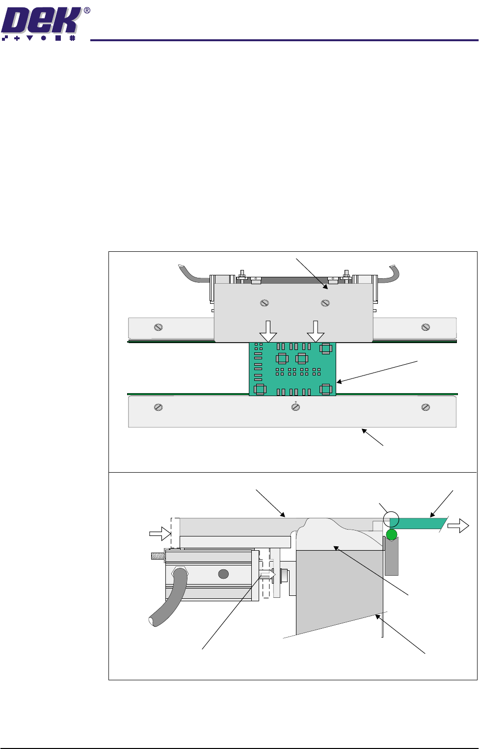
Figure 1-10 Board Snugger Clamping Arrangement
Board
Adjustable Snugger Plate
Fixed Snugger Plate
Plan View of Print Station Rail (Showing Board Clamped)
Side View of Print Station Rail (Showing Board Clamping Action)
Pneumatic Piston Extended
Board
Moving Rail
Movement of Adjustable
Snugger Plate
Movement
of Board
Rear Rail Guide
(Cutaway View)
I.O
Adjustable Snugger Plate Board Gripped by
Snugger Clamp